Lexus ES: Parts Location
PARTS LOCATION
ILLUSTRATION
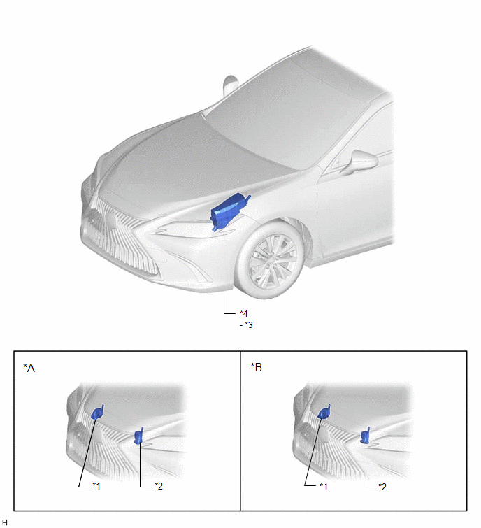
| *A | for Type A | *B | for Type B |
| *1 | HIGH PITCHED HORN ASSEMBLY | *2 | LOW PITCHED HORN ASSEMBLY |
| *3 | HORN RELAY | *4 | ENGINE ROOM RELAY BLOCK AND JUNCTION BLOCK ASSEMBLY - HORN FUSE |
ILLUSTRATION
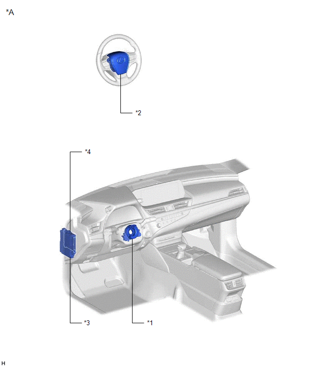
| *A | for LHD | - | - |
| *1 | SPIRAL CABLE SUB-ASSEMBLY | *2 | HORN BUTTON ASSEMBLY |
| *3 | INSTRUMENT PANEL JUNCTION BLOCK ASSEMBLY | *4 | MAIN BODY ECU (MULTIPLEX NETWORK BODY ECU) |
READ NEXT:
 Precaution
PRECAUTION PRECAUTION FOR DISCONNECTING CABLE FROM NEGATIVE AUXILIARY BATTERY TERMINAL NOTICE: When disconnecting the cable from the negative (-) auxiliary battery terminal, initialize the following s
Problem Symptoms Table
PROBLEM SYMPTOMS TABLE NOTICE: Before replacing the main body ECU (multiplex network body ECU), refer to Registration. for Gasoline Model: Click here for HV Model: Click here HINT: Use the tabl
System Diagram
SYSTEM DIAGRAM
SEE MORE:
Removal
REMOVAL CAUTION / NOTICE / HINT The necessary procedures (adjustment, calibration, initialization or registration) that must be performed after parts are removed and installed, or replaced during tire pressure warning ECU and receiver removal/installation are shown below. Necessary Procedures After
Installation
INSTALLATION CAUTION / NOTICE / HINT NOTICE: This procedure includes the installation of small-head bolts. Refer to Small-Head Bolts of Basic Repair Hint to identify the small-head bolts. Click here PROCEDURE 1. INSTALL CAM TIMING CONTROL MOTOR O-RING (a) Install a new cam timing control motor
© 2016-2026 Copyright www.lexguide.net
