Lexus ES: Installation
INSTALLATION
CAUTION / NOTICE / HINT
NOTICE:
This procedure includes the installation of small-head bolts. Refer to Small-Head Bolts of Basic Repair Hint to identify the small-head bolts.
Click here .gif)
PROCEDURE
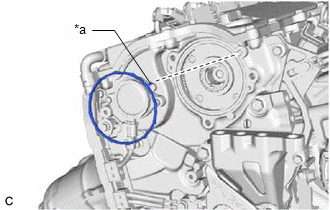
1. INSTALL CAM TIMING CONTROL MOTOR O-RING
| (a) Install a new cam timing control motor O-ring to the No. 2 timing gear cover assembly with the protrusion of the cam timing control motor O-ring oriented as shown in the illustration. |
|
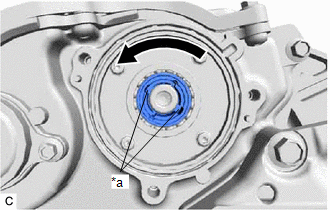
2. INSTALL CAM TIMING CONTROL MOTOR WITH EDU ASSEMBLY
HINT:
Perform "Inspection After Repair" after removing and installing, or replacing the cam timing control motor with EDU assembly.
Click here
| (a) Turn the cutout of the camshaft timing gear assembly eccentric shaft counterclockwise by hand, and set it to the maximum retard angle position. HINT:
|
|
| (b) Install the cam timing control motor with EDU assembly to the No. 2 timing gear cover assembly. NOTICE:
|
|
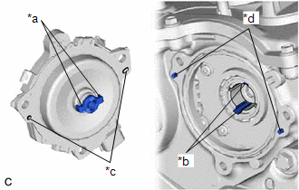
(c) Install the 3 bolts.
Torque:
21 N·m {214 kgf·cm, 15 ft·lbf}
(d) Connect the cam timing control motor with EDU assembly connector.
3. CONNECT CABLE TO NEGATIVE BATTERY TERMINAL
Click here
4. INSPECT FOR ENGINE OIL LEAK
Click here
5. INSTALL NO. 2 ENGINE COVER
Click here
6. INSTALL NO. 3 BRAKE TUBE CLAMP
Click here
7. INSTALL NO. 1 ENGINE COVER SUB-ASSEMBLY
Click here
8. PERFORM INITIALIZATION
(a) Perform "Inspection After Repair" after removing and installing, or replacing the cam timing control motor with EDU assembly.
Click here
READ NEXT:
 Crankshaft Position Sensor
ComponentsCOMPONENTS ILLUSTRATION *1 CRANKSHAFT POSITION SENSOR *2 O-RING N*m (kgf*cm, ft.*lbf): Specified torque ● Non-reusable part InstallationINSTALLATION CAUTION / NOT
Ecm
InstallationINSTALLATION PROCEDURE 1. INSTALL NO. 2 ECM BRACKET (a) Install the No. 2 ECM bracket to the ECM with the 2 screws. Torque: 4.5 N·m {46 kgf·cm, 40 in·lbf} 2. INSTALL NO. 1 ECM BRACKET
Engine Coolant Temperature Sensor
ComponentsCOMPONENTS ILLUSTRATION *1 ENGINE COOLANT TEMPERATURE SENSOR - - ● Non-reusable part - - RemovalREMOVAL CAUTION / NOTICE / HINT The necessary procedures (adjustmen
SEE MORE:
Disassembly
DISASSEMBLY CAUTION / NOTICE / HINT The necessary procedures (adjustment, calibration, initialization, or registration) that must be performed after parts are removed and installed, or replaced during rear door removal/installation are shown below. Necessary Procedure After Parts Removed/Installed/R
Components
COMPONENTS ILLUSTRATION *A for Front Side *B for Rear Side *1 FRONT SLIDING ROOF GARNISH LH *2 FRONT SLIDING ROOF GARNISH RH *3 SLIDING ROOF GLASS SUB-ASSEMBLY *4 SLIDING ROOF SIDE GARNISH LH *5 SLIDING ROOF SIDE GARNISH RH - - N*m (kgf*cm, ft.*lbf): Sp
