Lexus ES: Parts Location
Lexus ES (XZ10) Service Manual / Steering / Steering Column / Heated Steering Wheel System (for Gasoline Model) / Parts Location
PARTS LOCATION
ILLUSTRATION
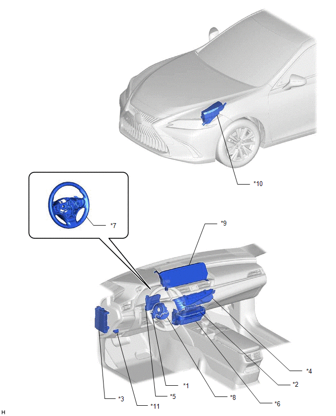
| *1 | SPIRAL CABLE SUB-ASSEMBLY | *2 | STEERING WHEEL HEATER SWITCH (REFRESHING SEAT SWITCH) |
| *3 | INSTRUMENT PANEL JUNCTION BLOCK ASSEMBLY - ECU-IG1 NO. 3 FUSE | *4 | AIR CONDITIONING CONTROL ASSEMBLY |
| *5 | AIR CONDITIONING AMPLIFIER ASSEMBLY | *6 | RADIO RECEIVER ASSEMBLY |
| *7 | STEERING WHEEL ASSEMBLY - STEERING WHEEL HEATER UNIT | *8 | HEATED STEERING WHEEL CONTROLLER (STEERING VIBRATION ECU) |
| *9 | MULTI-DISPLAY ASSEMBLY | *10 | NO. 1 ENGINE ROOM RELAY BLOCK AND NO. 1 JUNCTION BLOCK ASSEMBLY - STRG HTR FUSE - STRG HTR RELAY |
| *11 | DLC3 | - | - |
READ NEXT:
 System Diagram
SYSTEM DIAGRAM SYSTEM DIAGRAM Communication Table Sender Receiver Signal Line Radio Receiver Assembly Air Conditioning Amplifier Assembly
Steering wheel heater switch operation co
System Description
SYSTEM DESCRIPTION HEATED STEERING WHEEL SYSTEM (a) The heated steering wheel system heats the steering wheel assembly when the system is turned on using the steering wheel heater switch (refreshing s
How To Proceed With Troubleshooting
CAUTION / NOTICE / HINT HINT:
Use these procedures to troubleshoot the heated steering wheel system.
*: Use the Techstream.
PROCEDURE 1. VEHICLE BROUGHT TO WORKSHOP
NEXT
SEE MORE:
Removal
REMOVAL CAUTION / NOTICE / HINT The necessary procedures (adjustment, calibration, initialization, or registration) that must be performed after parts are removed and installed, or replaced during front frame assembly removal/installation are shown below. Necessary Procedure After Parts Removed/Inst
Rain Sensor Malfunction (B1400)
DESCRIPTION This DTC is stored when the rain sensor detects an internal malfunction. DTC No. Detection Item DTC Detection Condition Trouble Area Memory DTC Output from B1400 Rain Sensor Malfunction
IG power source voltage is 9.5 V or more
Either of the following is dete
© 2016-2026 Copyright www.lexguide.net
