Lexus ES: Removal
REMOVAL
CAUTION / NOTICE / HINT
The necessary procedures (adjustment, calibration, initialization, or registration) that must be performed after parts are removed and installed, or replaced during front frame assembly removal/installation are shown below.
Necessary Procedure After Parts Removed/Installed/Replaced (for HV Model:)| Replaced Part or Performed Procedure | Necessary Procedure | Effect/Inoperative Function when Necessary Procedure not Performed | Link |
|---|---|---|---|
|
*1: When performing learning using the Techstream.
Click here *2: for LED type turn signal light | |||
| Auxiliary battery terminal is disconnected/reconnected | Perform steering sensor zero point calibration | Lane control system | |
| Pre-collision system | |||
| Parking support brake system*1 | |||
| Lighting System | |||
| Memorize steering angle neutral point | Parking assist monitor system | | |
| Panoramic view monitor system | | ||
| Initialize power trunk lid system | Power trunk lid system | | |
| Replacement of ECM | Perform Vehicle Identification Number (VIN) registration | MIL illuminates | |
| Inspection After Repair |
| |
| Replacement of inverter with converter assembly | Resolver learning |
| |
| Replacement of hybrid vehicle transaxle assembly |
| ||
|
|
| |
| Suspension, tires, etc. (The vehicle height changes because of suspension or tire replacement) | Rear television camera assembly optical axis (Back camera position setting) | Parking assist monitor system | for Initialization: for Calibration: |
| Replacement of front bumper assembly | Front television camera view adjustment | Panoramic view monitor system | for Initialization: for Calibration: |
| Suspension, tires, etc. (The vehicle height changes because of suspension or tire replacement) |
| ||
| Replacement of headlight ECU sub-assembly LH |
| Lighting system | |
| Suspension, tires, etc. (The vehicle height changes because of suspension or tire replacement) | Perform headlight ECU sub-assembly LH initialization*2 | ||
| Front wheel alignment adjustment |
|
| |
| Rack and pinion power steering gear assembly |
|
| |
NOTICE:
- After the power switch is turned off, the radio receiver assembly records various types of memory and settings. As a result, after turning the power switch off, make sure to wait at least 85 seconds before disconnecting the cable from the negative (-) auxiliary battery terminal. (for Audio and Visual System)
- After the power switch is turned off, the radio receiver assembly records various types of memory and settings. As a result, after turning the power switch off, make sure to wait at least 85 seconds before disconnecting the cable from the negative (-) auxiliary battery terminal. (for Navigation System)
CAUTION / NOTICE / HINT
Necessary Procedure After Parts Removed/Installed/Replaced (for Gasoline Model:)| Replaced Part or Performed Procedure | Necessary Procedure | Effect/Inoperative Function when Necessary Procedure not Performed | Link |
|---|---|---|---|
|
*1: When performing learning using the Techstream.
Click here *2: When the ECM is replaced with a new one, reset memory is unnecessary. | |||
| Battery terminal is disconnected/reconnected | Perform steering sensor zero point calibration | Lane Control System | |
| Pre-collision System | |||
| Parking Support Brake System*1 | |||
| Lighting System | |||
| Memorize steering angle neutral point | Parking Assist Monitor System | | |
| Panoramic View Monitor System | | ||
| Initialize power trunk lid system | Power Trunk Lid System | | |
| Replacement of ECM | Vehicle Identification Number (VIN) registration | MIL comes on | |
| ECU communication ID registration (Immobiliser system) | Engine start function | | |
| Inspection after repair |
| |
| Replacement of automatic transaxle assembly |
|
| for Initialization: for Registration: |
| Replacement of ECM (If transaxle compensation code read from ECM) |
| ||
| Replacement of ECM (If transaxle compensation code not read from ECM) |
| ||
| Replacement of ECM | Code registration (Smart access system with push-button start (for Start Function, Gasoline Model) |
| |
| Replacement of automatic transaxle fluid | ATF thermal degradation estimate reset | The value of the Data List item "ATF Thermal Degradation Estimate" is not estimated correctly | |
| Suspension, tires, etc. (The vehicle height changes because of suspension or tire replacement) | Rear television camera assembly optical axis adjustment (Back camera position setting) | Parking Assist Monitor System | for Initialization: for Calibration: |
| Perform headlight ECU sub-assembly LH initialization | Lighting system | | |
| Replacement of front bumper assembly | Front television camera view adjustment | Panoramic View Monitor System | for Initialization: for Calibration: |
| Suspension, tires, etc. (The vehicle height changes because of suspension or tire replacement) |
| ||
| Front wheel alignment adjustment |
|
| |
| Rack and pinion power steering gear assembly |
|
| |
NOTICE:
- After the engine switch is turned off, the radio receiver assembly records various types of memory and settings. As a result, after turning the engine switch off, make sure to wait at least 85 seconds before disconnecting the cable from the negative (-) battery terminal. (for Audio and Visual System)
- After the engine switch is turned off, the radio receiver assembly records various types of memory and settings. As a result, after turning the engine switch off, make sure to wait at least 85 seconds before disconnecting the cable from the negative (-) battery terminal. (for Navigation System)
PROCEDURE
1. REMOVE ENGINE ASSEMBLY WITH TRANSAXLE
for A25A-FXS: Click here .gif)
for 2GR-FKS: Click here
2. REMOVE FUEL DELIVERY GUARD (for A25A-FXS)
Click here
3. INSTALL ENGINE HANGERS
for A25A-FXS: Click here
for 2GR-FKS: Click here
4. REMOVE STEERING GEAR HEAT INSULATOR (for A25A-FXS)
Click here
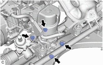
5. DISCONNECT WIRE HARNESS
Click here
6. REMOVE FRONT FRAME ASSEMBLY
| (a) Remove the 3 nuts and separate the front engine mounting insulator from the front frame assembly. |
|
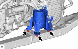
| (b) Remove the 4 nuts and separate the rear engine mounting insulator from the front frame assembly. |
|
7. REMOVE FRONT STABILIZER BAR WITH BRACKET
Click here
8. REMOVE RACK AND PINION POWER STEERING GEAR ASSEMBLY
Click here
9. REMOVE FRONT LOWER NO. 1 SUSPENSION ARM SUB-ASSEMBLY LH
| (a) Remove the 3 bolts, nut and front lower No. 1 suspension arm sub-assembly LH from the front frame assembly. NOTICE: Because the nut has its own stopper, do not turn the nut. Loosen the bolt with the nut secured. |
|
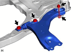
(b) Remove the front lower arm bushing stopper from the front lower No. 1 suspension arm sub-assembly.
10. REMOVE FRONT LOWER NO. 1 SUSPENSION ARM SUB-ASSEMBLY RH
HINT:
Perform the same procedure as for the LH side.
11. REMOVE NO. 2 EXHAUST PIPE SUPPORT BRACKET
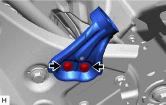
| (a) Remove the 2 bolts and No. 2 exhaust pipe support bracket from the front frame assembly. |
|
12. REMOVE FRONT SUSPENSION MEMBER DYNAMIC DAMPER (for 2GR-FKS)
| (a) Remove the 2 bolts and front suspension member dynamic damper from the front frame assembly. |
|
13. REMOVE BOLT (for A25A-FXS)
(a) Remove the 2 bolts from the front frame assembly.
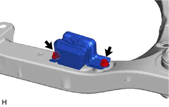
14. REMOVE FRONT SUSPENSION MEMBER BODY MOUNTING FRONT STOPPER
(a) Remove the 2 front suspension member body mounting front stoppers from the front frame assembly.
15. REMOVE FRONT SUSPENSION MEMBER BODY MOUNTING REAR STOPPER
(a) Remove the 2 front suspension member body mounting rear stoppers from the front frame assembly.
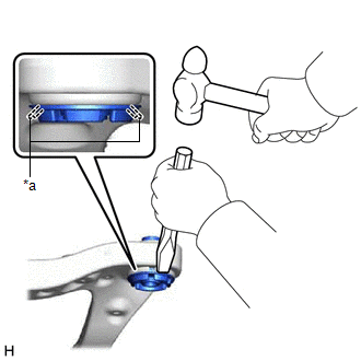
16. REMOVE FRONT SUSPENSION MEMBER BODY MOUNTING FRONT CUSHION (for LH Side)
| (a) Using a chisel and hammer, kink the flange of the front suspension member body mounting front cushion as shown in the illustration. |
|
(b) Apply lubricant to the contact surfaces of the front suspension member body mounting front cushion.
| (c) Install SST as shown in the illustration. SST: 09830-10010 09830-01010 09830-01040 09830-01050 SST: 09950-40011 09951-04020 09952-04010 09954-04010 09955-04011 09958-04011 NOTICE: Apply molybdenum grease to the threads and tip of the SST center bolt before use. |
|
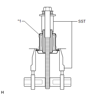
(d) Turn the SST center bolt as shown in the illustration to create a clearance between the front suspension member body mounting front cushion and the front frame assembly.

| *a | Hold |
.png) | Turn |
(e) While applying lubricant to the front suspension member body mounting front cushion through the clearance, gradually remove the front suspension member body mounting front cushion.
NOTICE:
- Tighten SST slowly and evenly.
- Be careful as the mounting cushion may fly out.
- The mounting cushion cannot be reused.
17. REMOVE FRONT SUSPENSION MEMBER BODY MOUNTING FRONT CUSHION (for RH Side)
HINT:
Perform the same procedure as for the LH side.
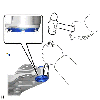
18. REMOVE FRONT SUSPENSION MEMBER BODY MOUNTING REAR CUSHION LH
| (a) Using a chisel and hammer, kink the flange of the front suspension member body mounting rear cushion LH as shown in the illustration. |
|
(b) Apply lubricant to the contact surfaces of the front suspension member body mounting rear cushion LH.
| (c) Install SST as shown in the illustration. SST: 09830-10010 09830-01010 09830-01040 09830-01050 SST: 09950-40011 09951-04020 09952-04010 09954-04010 09955-04011 09958-04011 NOTICE: Apply molybdenum grease to the threads and tip of the SST center bolt before use. |
|

(d) Turn the SST center bolt as shown in the illustration to create a clearance between the front suspension member body mounting rear cushion LH and the front frame assembly.

| *a | Hold |
| | Turn |
(e) While applying lubricant to the front suspension member body mounting rear cushion LH through the clearance, gradually remove the front suspension member body mounting rear cushion LH.
NOTICE:
- Tighten SST slowly and evenly.
- Be careful as the mounting cushion may fly out.
- The mounting cushion cannot be reused.
19. REMOVE FRONT SUSPENSION MEMBER BODY MOUNTING REAR CUSHION
HINT:
Perform the same procedure as for the front suspension member body mounting rear cushion LH.
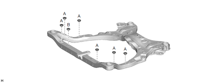
20. REMOVE HOLE PLUG
(a) Remove the 7 hole plugs from the front frame assembly.
HINT:
There are 2 different shapes of hole plug.
READ NEXT:
 Installation
INSTALLATION PROCEDURE 1. INSTALL HOLE PLUG (a) Install the 7 hole plugs to the front frame assembly. HINT: There are 2 different shapes of hole plug. 2. INSTALL FRONT SUSPENSION MEMBER BODY MOUNTING
Installation
INSTALLATION PROCEDURE 1. INSTALL HOLE PLUG (a) Install the 7 hole plugs to the front frame assembly. HINT: There are 2 different shapes of hole plug. 2. INSTALL FRONT SUSPENSION MEMBER BODY MOUNTING
SEE MORE:
Precaution
PRECAUTION PRECAUTION FOR DISCONNECTING CABLE FROM NEGATIVE BATTERY TERMINAL NOTICE: When disconnecting the cable from the negative (-) battery terminal, initialize the following systems after the cable is reconnected. System Name See Procedure Lane Control System (for Gasoline Model)
Precaution
PRECAUTION PRECAUTION FOR DISCONNECTING CABLE FROM NEGATIVE AUXILIARY BATTERY TERMINAL NOTICE: When disconnecting the cable from the negative (-) auxiliary battery terminal, initialize the following system(s) after the cable is reconnected: System See Procedure Lane Control System (for HV M
