Lexus ES: Parts Location
PARTS LOCATION
ILLUSTRATION
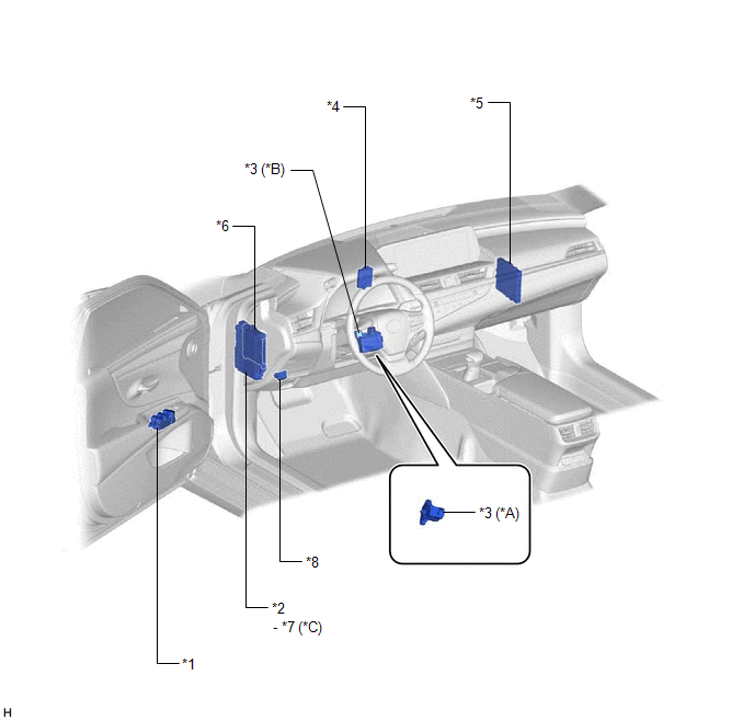
| *A | for Manual Tilt and Manual Telescopic Steering Column | *B | for Power Tilt and Power Telescopic Steering Column |
| *C | w/ Power Trunk Lid System | - | - |
| *1 | MULTIPLEX NETWORK MASTER SWITCH ASSEMBLY | *2 | INSTRUMENT PANEL JUNCTION BLOCK ASSEMBLY - ECU-B NO. 2 FUSE - DOOR F/L FUSE - DOOR F/R FUSE - DOOR R/L FUSE - DOOR R/R FUSE - S/ROOF FUSE - STRG LOCK FUSE - ECU-B NO. 1 FUSE |
| *3 | STEERING LOCK ECU (STEERING LOCK ACTUATOR OR UPPER BRACKET ASSEMBLY) | *4 | ID CODE BOX (IMMOBILISER CODE ECU) |
| *5 | CERTIFICATION ECU (SMART KEY ECU ASSEMBLY) | *6 | MAIN BODY ECU (MULTIPLEX NETWORK BODY ECU) |
| *7 | ECU-DCC NO. 2 FUSE | *8 | DLC3 |
ILLUSTRATION
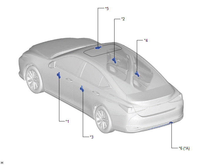
| *A | w/ Power Trunk Lid System | - | - |
| *1 | POWER WINDOW REGULATOR MOTOR ASSEMBLY (DRIVER DOOR) | *2 | POWER WINDOW REGULATOR MOTOR ASSEMBLY (FRONT PASSENGER DOOR) |
| *3 | POWER WINDOW REGULATOR MOTOR ASSEMBLY (REAR LH DOOR) | *4 | POWER WINDOW REGULATOR MOTOR ASSEMBLY (REAR RH DOOR) |
| *5 | SLIDING ROOF ECU (SLIDING ROOF DRIVE GEAR SUB-ASSEMBLY) | *6 | KICK DOOR CONTROL SENSOR |
READ NEXT:
 Precaution
PRECAUTION PRECAUTION FOR DISCONNECTING CABLE FROM NEGATIVE AUXILIARY BATTERY TERMINAL NOTICE: When disconnecting the cable from the negative (-) auxiliary battery terminal, initialize the following s
Lost Communication with Power Source Control (B278C)
DESCRIPTION When an internal malfunction is detected in the certification ECU (smart key ECU assembly), this DTC is stored. DTC No. Detection Item DTC Detection Condition Trouble Area B27
SEE MORE:
Deceleration Sensor (C1245)
DESCRIPTION The parking brake ECU (brake actuator assembly) receives vehicle tilt angle information from the deceleration sensor (airbag ECU assembly) via CAN communication. DTC No. Detection Item DTC Detection Condition Trouble Area Memory Note C1245 Deceleration Sensor One of
Components
COMPONENTS ILLUSTRATION *1 COOL AIR INTAKE DUCT SEAL *2 FRONT FENDER SPLASH SHIELD SUB-ASSEMBLY *3 HOOD STAY BRACKET *4 HOOD SUPPORT ASSEMBLY *5 HOOD SUPPORT BRACKET *6 NO. 3 COWL TOP PANEL INSULATOR N*m (kgf*cm, ft.*lbf): Specified torque - -
