
Lexus ES: Parts Location
PARTS LOCATION
ILLUSTRATION
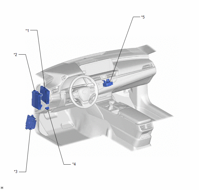
| *1 | HYBRID VEHICLE CONTROL ECU | *2 | INSTRUMENT PANEL JUNCTION BLOCK ASSEMBLY - ECU-B NO. 1 FUSE |
| *3 | NO. 4 RELAY BLOCK - IGCT NO. 2 FUSE - PM-IGCT FUSE - BATT FAN FUSE | *4 | DLC3 |
| *5 | NO. 3 RELAY BLOCK - IGCT RELAY | - | - |
ILLUSTRATION
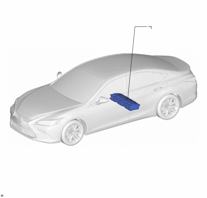
| *1 | HV BATTERY | - | - |
ILLUSTRATION
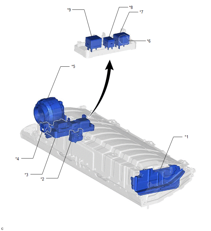
| *1 | BATTERY ECU ASSEMBLY | *2 | HYBRID BATTERY TERMINAL BLOCK |
| *3 | HV BATTERY JUNCTION BLOCK ASSEMBLY | *4 | SERVICE PLUG GRIP |
| *5 | BATTERY COOLING BLOWER ASSEMBLY | *6 | BATTERY CURRENT SENSOR |
| *7 | SMRB | *8 | SMRP |
| *9 | SMRG | - | - |
ILLUSTRATION
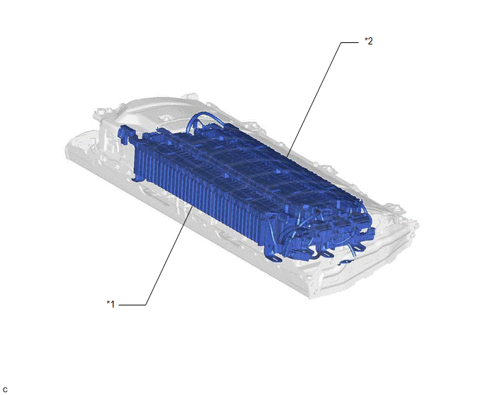
| *1 | NO. 1 HV SUPPLY STACK SUB-ASSEMBLY | *2 | NO. 2 HV SUPPLY STACK SUB-ASSEMBLY |
READ NEXT:
 System Diagram
SYSTEM DIAGRAM
How To Proceed With Troubleshooting
CAUTION / NOTICE / HINT HINT:
*: Use the Techstream
Use the following procedure to troubleshoot the hybrid battery system.
PROCEDURE 1. VEHICLE BROUGHT TO WORKSHOP
NEXT
Check For Intermittent Problems
CHECK FOR INTERMITTENT PROBLEMS CHECK FOR INTERMITTENT PROBLEMS (a) Perform a simulation test. (1) For the simulation test, reproduce the driving conditions that were present when the problem occurred
SEE MORE:
Internal Control Module Throttle Position Performance Internal Electronic Failure (P060E49,P061E49)
MONITOR DESCRIPTION The ECM monitors the signals received from the No. 1 throttle position sensor and stop light switch assembly. As the ECM monitors the STP signal of the stop light switch assembly and the VTA1 signal of the No. 1 throttle position sensor, if these signals do not correlate, a DTC w
Precaution
PRECAUTION PRECAUTION FOR DISCONNECTING CABLE FROM NEGATIVE AUXILIARY BATTERY TERMINAL NOTICE: When disconnecting the cable from the negative (-) auxiliary battery terminal, initialize the following systems after the cable is reconnected. System Name See Procedure Lane Control System (for H
© 2016-2026 Copyright www.lexguide.net
