Lexus ES: Parts Location
Lexus ES (XZ10) Service Manual / Engine & Hybrid System / 2gr-fks (intake / Exhaust) / Intake System / Parts Location
PARTS LOCATION
ILLUSTRATION
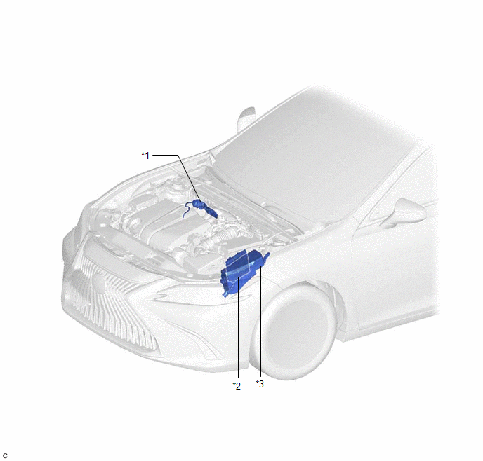
| *1 | INTAKE AIR CONTROL VALVE (for ACIS) | *2 | ECM |
| *3 | ENGINE ROOM RELAY BLOCK AND JUNCTION BLOCK ASSEMBLY - EFI NO. 1 FUSE | - | - |
READ NEXT:
 System Diagram
SYSTEM DIAGRAM *1 Throttle Body with Motor Assembly *2 Intake Air Control Valve (for ACIS) *3 Intake Air Control Valve Actuator (for ACIS) *4 ECM *5 Vacuum Switching Valve (f
On-vehicle Inspection
ON-VEHICLE INSPECTION CAUTION / NOTICE / HINT The necessary procedures (adjustment, calibration, initialization or registration) that must be performed after parts are removed and installed, or replac
Vacuum Switching Valve(for Acis)
ComponentsCOMPONENTS ILLUSTRATION *1 NO. 1 VACUUM SWITCHING VALVE ASSEMBLY (for ACIS) *2 VACUUM HOSE SUB-ASSEMBLY *3 V-BANK COVER SUB-ASSEMBLY - - N*m (kgf*cm, ft.*lbf): Sp
SEE MORE:
Freeze Frame Data
FREEZE FRAME DATA CHECK FREEZE FRAME DATA HINT: The ECU records vehicle and driving condition information as freeze frame data the moment a DTC is stored. (a) Connect the Techstream to the DLC3. (b) Turn the engine switch on (IG). (c) Turn the Techstream on. (d) Enter the following menus: Powertrain
Left Front Wheel Speed Sensor Signal Stuck High (C050024)
DESCRIPTION Refer to DTC C050012 Click here DTC No. Detection Item DTC Detection Condition Trouble Area C050024 Left Front Wheel Speed Sensor Signal Stuck High The speed sensor signal is not within the specified range for 5 seconds or more. Front speed sensor LH CAUTION / NOT
© 2016-2026 Copyright www.lexguide.net
