Lexus ES: Vacuum Switching Valve(for Acis)
Components
COMPONENTS
ILLUSTRATION
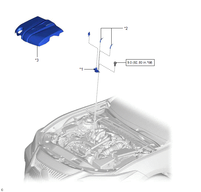
| *1 | NO. 1 VACUUM SWITCHING VALVE ASSEMBLY (for ACIS) | *2 | VACUUM HOSE SUB-ASSEMBLY |
| *3 | V-BANK COVER SUB-ASSEMBLY | - | - |
.png) | N*m (kgf*cm, ft.*lbf): Specified torque | - | - |
Removal
REMOVAL
PROCEDURE
1. REMOVE V-BANK COVER SUB-ASSEMBLY
Click here .gif)
2. REMOVE NO. 1 VACUUM SWITCHING VALVE ASSEMBLY (for ACIS)
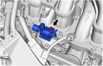
| (a) Disconnect the No. 1 vacuum switching valve assembly (for ACIS) connector. |
|
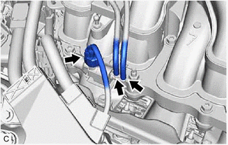
(b) Disconnect the 2 vacuum hose assemblies from the No. 1 vacuum switching valve assembly (for ACIS).
| (c) Remove the bolt and No. 1 vacuum switching valve assembly (for ACIS) from the intake air surge tank assembly. |
|
Inspection
INSPECTION
PROCEDURE
1. INSPECT NO. 1 VACUUM SWITCHING VALVE ASSEMBLY (for ACIS)
| (a) Measure the resistance according to the value(s) in the table below. Standard Resistance:
If the result is not as specified, replace the No. 1 vacuum switching valve assembly (for ACIS). |
|
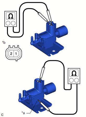
(b) Check the No. 1 vacuum switching valve assembly (for ACIS) operation.
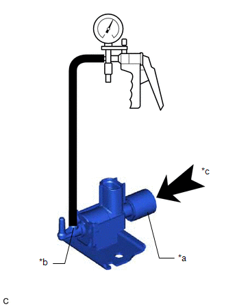
| (1) When vacuum is applied to the port (E), check that air is sucked into the filter. If the result is not as specified, replace the No. 1 vacuum switching valve assembly (for ACIS). |
|
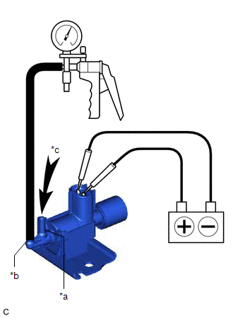
| (2) Apply battery voltage across the terminals. When vacuum is applied to the port (F), check that air is sucked into the port (E). If the result is not as specified, replace the No. 1 vacuum switching valve assembly (for ACIS). |
|
Installation
INSTALLATION
PROCEDURE
1. INSTALL NO. 1 VACUUM SWITCHING VALVE ASSEMBLY (for ACIS)
(a) Install the No. 1 vacuum switching valve assembly (for ACIS) to the intake air surge tank assembly with the bolt.
Torque:
9.0 N·m {92 kgf·cm, 80 in·lbf}
(b) Connect the 2 vacuum hose sub-assemblies to the No. 1 vacuum switching valve assembly (for ACIS).
(c) Connect the No. 1 vacuum switching valve assembly (for ACIS) connector.
2. INSTALL V-BANK COVER SUB-ASSEMBLY
Click here .gif)
READ NEXT:
 Lubrication System
On-vehicle InspectionON-VEHICLE INSPECTION PROCEDURE 1. CHECK ENGINE OIL LEVEL (a) Warm up and stop the engine, then wait for 5 minutes. (b) Check that the engine oil level is between the low level a
Oil And Oil Filter
ComponentsCOMPONENTS ILLUSTRATION *A Type A *B Type B *1 FRONT WHEEL OPENING EXTENSION PAD LH *2 FRONT WHEEL OPENING EXTENSION PAD RH *3 NO. 1 ENGINE UNDER COVER *4 NO.
SEE MORE:
Reassembly
REASSEMBLY CAUTION / NOTICE / HINT HINT:
Use the same procedure for the RH side and LH side.
The following procedure is for the LH side.
PROCEDURE 1. PRECAUTION NOTICE: After turning the engine switch (for Gasoline Model) or power switch (for HV Model) off, waiting time may be required befor
Drive Motor Inverter Temperature Sensor "A" Circuit Short to Ground (P0AED11,P0AED15)
DESCRIPTION The motor generator control ECU (MG ECU), which is built into in the inverter with converter assembly, detects the temperature of the motor inverter using the motor inverter temperature sensor. The inverter cooling system operates independently of the engine cooling system. The motor gen
