Lexus ES: On-vehicle Inspection
ON-VEHICLE INSPECTION
CAUTION / NOTICE / HINT
The necessary procedures (adjustment, calibration, initialization or registration) that must be performed after parts are removed and installed, or replaced when repairing air leaks in the intake system are shown below.
Necessary Procedures After Parts Removed/Installed/Replaced| Replaced Part or Performed Procedure | Necessary Procedure | Effect/Inoperative Function when Necessary Procedure not Performed | Link |
|---|---|---|---|
| Air leaks from intake system is repaired | Inspection After Repair |
| |
PROCEDURE
1. INSPECT INTAKE SYSTEM
CAUTION:
To prevent injury due to contact with an operating V-ribbed belt or cooling fan, keep your hands and clothing away from the V-ribbed belt and cooling fans when working in the engine compartment with the engine running or the engine switch on (IG).
.png)
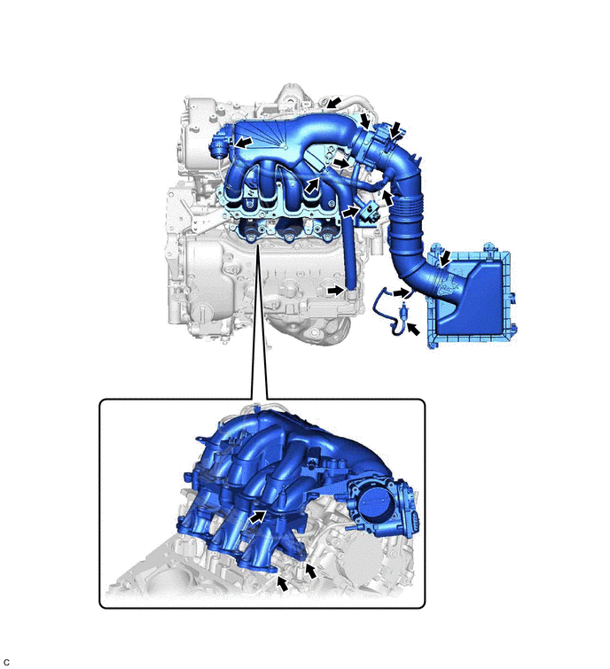
(a) Check that there are no vacuum leaks at the points shown in the illustration.
HINT:
Perform "Inspection After Repair" after repairing vacuum leaks in the intake system.
Click here .gif)
2. INSPECT INTAKE AIR CONTROL VALVE (for ACIS)
(a) Connect the Techstream to the DLC3.
(b) Turn the engine switch on (IG).
(c) Turn the Techstream on.
| (d) Enter the following menus: Powertrain / Engine / Active Test / Activate the VSV for Intake Control. Powertrain > Engine > Active Test
|
|
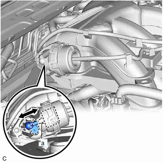
(e) When Activate the VSV for Intake Control is set to on, check that the actuator rod operates.
If the actuator rod does not operate, inspect the intake air control valve (for ACIS) and No. 1 vacuum switching valve assembly (for ACIS).
-
Inspect intake air control valve (for ACIS)
Click here
-
Inspect No. 1 vacuum switching valve assembly (for ACIS)
Click here
(f) When Activate the VSV for Intake Control is set to off, check that the actuator rod returns to its original position.
If the actuator rod does not return to its original position, inspect the intake air control valve (for ACIS) and No. 1 vacuum switching valve assembly (for ACIS).
-
Inspect intake air control valve (for ACIS)
Click here
-
Inspect No. 1 vacuum switching valve assembly (for ACIS)
Click here
3. PERFORM INITIALIZATION
(a) Perform "Inspection After Repair" after repairing vacuum leaks in the intake system.
Click here
READ NEXT:
 Vacuum Switching Valve(for Acis)
ComponentsCOMPONENTS ILLUSTRATION *1 NO. 1 VACUUM SWITCHING VALVE ASSEMBLY (for ACIS) *2 VACUUM HOSE SUB-ASSEMBLY *3 V-BANK COVER SUB-ASSEMBLY - - N*m (kgf*cm, ft.*lbf): Sp
Lubrication System
On-vehicle InspectionON-VEHICLE INSPECTION PROCEDURE 1. CHECK ENGINE OIL LEVEL (a) Warm up and stop the engine, then wait for 5 minutes. (b) Check that the engine oil level is between the low level a
SEE MORE:
Installation
INSTALLATION CAUTION / NOTICE / HINT HINT:
Use the same procedure for the RH side and LH side.
The following procedure is for the LH side.
PROCEDURE 1. INSTALL REAR DOOR WINDOW FRAME MOULDING SUB-ASSEMBLY (a) Engage the guide to temporarily install the rear door window frame moulding sub-ass
Removal
REMOVAL CAUTION / NOTICE / HINT The necessary procedures (adjustment, calibration, initialization or registration) that must be performed after parts are removed and installed, or replaced during front door opening trim weatherstrip removal/installation are shown below. Necessary Procedure After Par
