Lexus ES: System Diagram
Lexus ES (XZ10) Service Manual / Engine & Hybrid System / 2gr-fks (intake / Exhaust) / Intake System / System Diagram
SYSTEM DIAGRAM
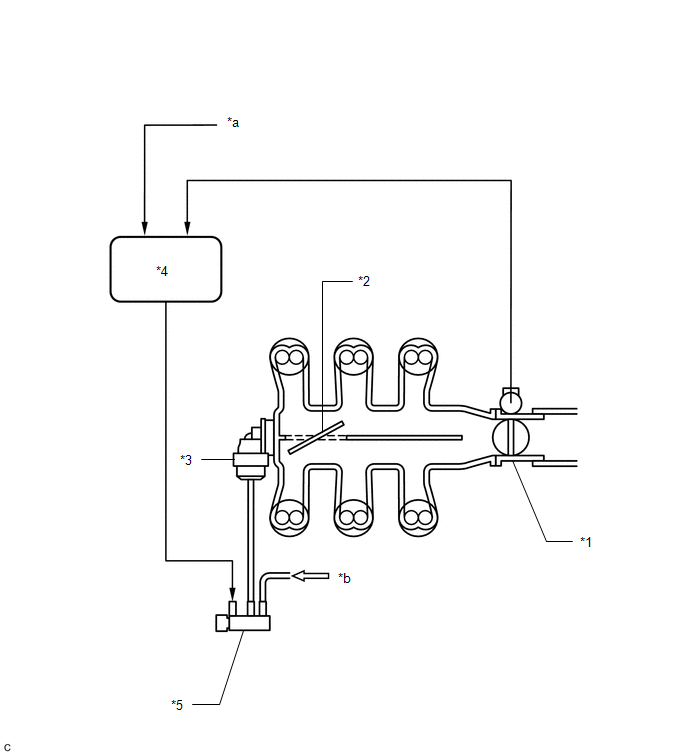
| *1 | Throttle Body with Motor Assembly | *2 | Intake Air Control Valve (for ACIS) |
| *3 | Intake Air Control Valve Actuator (for ACIS) | *4 | ECM |
| *5 | Vacuum Switching Valve (for ACIS) | - | - |
| *a | Engine Speed Signal | *b | from Vacuum Pump |

READ NEXT:
 On-vehicle Inspection
ON-VEHICLE INSPECTION CAUTION / NOTICE / HINT The necessary procedures (adjustment, calibration, initialization or registration) that must be performed after parts are removed and installed, or replac
Vacuum Switching Valve(for Acis)
ComponentsCOMPONENTS ILLUSTRATION *1 NO. 1 VACUUM SWITCHING VALVE ASSEMBLY (for ACIS) *2 VACUUM HOSE SUB-ASSEMBLY *3 V-BANK COVER SUB-ASSEMBLY - - N*m (kgf*cm, ft.*lbf): Sp
SEE MORE:
Side Camera Current Malfunction (C1684)
DESCRIPTION This DTC is stored if the parking assist ECU judges as a result of its self check that a synchronization problem is occurring in the image signal sent from the passenger side television camera assembly to the parking assist ECU. DTC No. Detection Item DTC Detection Condition Tro
System Diagram
SYSTEM DIAGRAM w/ Parking Assist Monitor System w/ Panoramic View Monitor System w/ Manual (SOS) Switch w/o Manual (SOS) Switch for 10 Speakers for 17 Speakers
© 2016-2026 Copyright www.lexguide.net
