Lexus ES: Parts Location
Lexus ES (XZ10) Service Manual / Drivetrain / Gf1a (transfer / 4wd / Awd) / Dynamic Torque Control Awd System / Parts Location
PARTS LOCATION
ILLUSTRATION
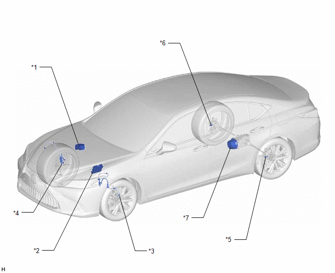
| *1 | BRAKE ACTUATOR ASSEMBLY - SKID CONTROL ECU | *2 | ECM |
| *3 | FRONT SPEED SENSOR LH | *4 | FRONT SPEED SENSOR RH |
| *5 | REAR SKID CONTROL SENSOR LH | *6 | REAR SKID CONTROL SENSOR RH |
| *7 | TRANSMISSION COUPLING ASSEMBLY - 4WD LINEAR SOLENOID | - | - |
ILLUSTRATION
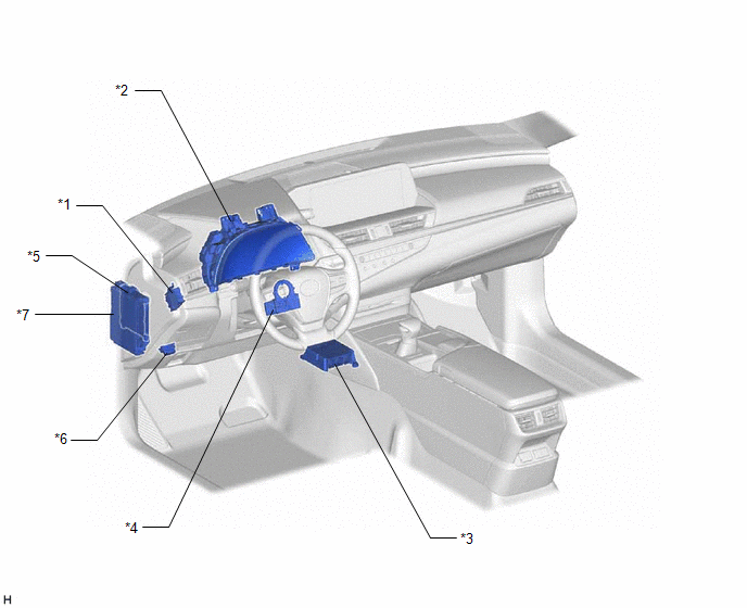
| *1 | 4WD ECU ASSEMBLY | *2 | COMBINATION METER ASSEMBLY - AWD WARNING MESSAGE (MULTI-INFORMATION DISPLAY) |
| *3 | AIRBAG ECU ASSEMBLY - YAW RATE AND ACCELERATION SENSOR | *4 | STEERING SENSOR |
| *5 | MAIN BODY ECU (MULTIPLEX NETWORK BODY ECU) | *6 | DLC3 |
| *7 | INSTRUMENT PANEL JUNCTION BLOCK ASSEMBLY - ECU-DCC NO. 1 FUSE - ECU-IG1 NO. 2 FUSE | - | - |
READ NEXT:
 Problem Symptoms Table
PROBLEM SYMPTOMS TABLE HINT:
Use the table below to help determine the cause of problem symptoms. If multiple suspected areas are listed, the potential causes of the symptoms are listed in order of
System Diagram
SYSTEM DIAGRAM
Terminals Of Ecu
TERMINALS OF ECU CHECK 4WD ECU ASSEMBLY (a) Measure the voltage and resistance of the connector. Terminal No. (Symbol) Wiring Color Terminal Description Condition Specified Condition G
SEE MORE:
Transmitter ID not Received (Main) (C2126)
DESCRIPTION If ID registration via the automatic ID registration function is canceled or the tire pressure warning ECU and receiver does not receive data from the tire pressure warning valve and transmitters after the tire pressure warning valve and transmitter ID registration is completed using the
Hybrid/EV Battery Cooling Fan 1 Circuit Short to Ground (P0A8111)
DESCRIPTION The battery cooling blower assembly speed is controlled by the battery ECU assembly. Power is supplied to the battery cooling blower assembly when the MREL terminal of the hybrid vehicle control ECU turns on the IGCT relay. The battery ECU assembly sends command signals (SI0) to the batt
© 2016-2026 Copyright www.lexguide.net
