Lexus ES: Front Left Microphone Circuit Component Internal Failure (B1AA296,B1AA31C)
DESCRIPTION
These DTCs are stored when a malfunction occurs in the No. 1 active noise control microphone system.
| DTC No. | Detection Item | DTC Detection Condition | Trouble Area |
|---|---|---|---|
| B1AA296 | Front Left Microphone Circuit Component Internal Failure | Stereo component equalizer assembly detects malfunction in No. 1 active noise control microphone for 4 seconds or more continuously when engine speed is 1200 rpm or more* |
|
| B1AA31C | Front Left Microphone Circuit Circuit Voltage Out of Range | Stereo component equalizer assembly detects No. 1 active noise control microphone connection malfunction for 4 seconds or more continuously* |
|
HINT:
*: Malfunction monitoring is not performed under the following conditions, in order to prevent erroneous detection.
- After power switch is turned on (ACC) for 3 seconds or more.
- After the auxiliary battery voltage returns to normal for 3 seconds.
- Before 3 seconds have elapsed after auxiliary battery voltage has returned to normal.
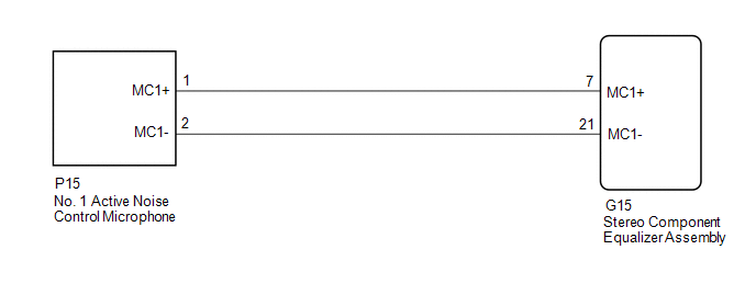
WIRING DIAGRAM
PROCEDURE
| 1. | CLEAR DTC |
(a) Clear the DTCs.
Body Electrical > Active Noise Control > Clear DTCs
|

| 2. | CHECK FOR DTC |
(a) Check for DTCs with all of the detection conditions met.
Body Electrical > Active Noise Control > Trouble CodesOK:
No DTCs are output.
| OK |  | USE SIMULATION METHOD TO CHECK |
|
| 3. | CHECK HARNESS AND CONNECTOR (STEREO COMPONENT EQUALIZER ASSEMBLY - NO. 1 ACTIVE NOISE CONTROL MICROPHONE) |
(a) Disconnect the G15 stereo component equalizer assembly connector.
(b) Disconnect the P15 No. 1 active noise control microphone connector.
(c) Measure the resistance according to the value(s) in the table below.
Standard Resistance:
| Tester Connection | Condition | Specified Condition |
|---|---|---|
| G15-7 (MC1+) - P15-1 (MC1+) | Always | Below 1 Ω |
| G15-21 (MC1-) - P15-2 (MC1-) | Always | Below 1 Ω |
| G15-7 (MC1+) or P15-1 (MC1+) - Body ground | Always | 10 kΩ or higher |
| G15-21 (MC1-) or P15-2 (MC1-) - Body ground | Always | 10 kΩ or higher |
| NG | | REPAIR OR REPLACE HARNESS OR CONNECTOR |
|
| 4. | REPLACE NO. 1 ACTIVE NOISE CONTROL MICROPHONE |
(a) Replace the No. 1 active noise control microphone with a new or known good one.
Click here .gif)
|
| 5. | CLEAR DTC |
(a) Clear the DTCs.
Body Electrical > Active Noise Control > Clear DTCs
|
| 6. | CHECK FOR DTC |
(a) Check for DTCs with all of the detection conditions met.
Body Electrical > Active Noise Control > Trouble CodesOK:
No DTCs are output.
| OK | | END (NO. 1 ACTIVE NOISE CONTROL MICROPHONE IS DEFECTIVE) |
| NG | | REPLACE STEREO COMPONENT EQUALIZER ASSEMBLY |
READ NEXT:
 Front Right Microphone Circuit Component Internal Failure (B1AA696,B1AA71C)
DESCRIPTION These DTCs are stored when a malfunction occurs in the No. 2 active noise control microphone system. DTC No. Detection Item DTC Detection Condition Trouble Area B1AA696 Fron
Rear Center Microphone Circuit Component Internal Failure (B1AAA96,B1AAB1C)
DESCRIPTION These DTCs are stored when a malfunction occurs in the No. 3 active noise control microphone system. DTC No. Detection Item DTC Detection Condition Trouble Area B1AAA96 Rear
Data List / Active Test
DATA LIST / ACTIVE TEST DATA LIST NOTICE: In the following table, the values listed under "Normal Condition" are reference values. Do not depend solely on these reference values when deciding whether
SEE MORE:
Data List / Active Test
DATA LIST / ACTIVE TEST DATA LIST NOTICE: In the table below, the values listed under "Normal Condition" are reference values. Do not depend solely on these reference values when deciding whether a part is faulty or not. (a) Connect the Techstream to the DLC3. (b) Turn the engine switch on (IG). (c)
How To Proceed With Troubleshooting
CAUTION / NOTICE / HINT HINT:
Use the following procedure to troubleshoot the tire pressure warning system.
Make sure that the wireless door lock control system has exited diagnostic mode before performing the following procedure.
*: Use the Techstream.
PROCEDURE 1. VEHICLE BROUGHT T
