Lexus ES: Parts Location
PARTS LOCATION
ILLUSTRATION
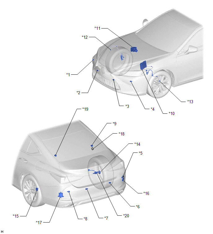
| *1 | FRONT CORNER ULTRASONIC SENSOR RH | *2 | FRONT CENTER ULTRASONIC SENSOR RH |
| *3 | FRONT CENTER ULTRASONIC SENSOR LH | *4 | FRONT CORNER ULTRASONIC SENSOR LH |
| *5 | REAR CORNER ULTRASONIC SENSOR RH | *6 | REAR CENTER ULTRASONIC SENSOR RH |
| *7 | REAR CENTER ULTRASONIC SENSOR LH | *8 | REAR CORNER ULTRASONIC SENSOR LH |
| *9 | NO. 2 CLEARANCE WARNING BUZZER | *10 | ECM |
| *11 | BRAKE ACTUATOR ASSEMBLY - SKID CONTROL ECU | *12 | FRONT SPEED SENSOR RH |
| *13 | FRONT SPEED SENSOR LH | *14 | REAR AXLE HUB AND BEARING ASSEMBLY RH - REAR SPEED SENSOR RH |
| *15 | REAR AXLE HUB AND BEARING ASSEMBLY LH - REAR SPEED SENSOR LH | *16 | BLIND SPOT MONITOR SENSOR RH (MASTER) (w/ Blind Spot Monitor System) |
| *17 | BLIND SPOT MONITOR SENSOR LH (SLAVE) (w/ Blind Spot Monitor System) | *18 | No. 24 JUNCTION CONNECTOR |
| *19 | RCTA BUZZER (BLIND SPOT MONITOR BUZZER) (w/ Blind Spot Monitor System) | *20 | REAR TELEVISION CAMERA ASSEMBLY |
ILLUSTRATION
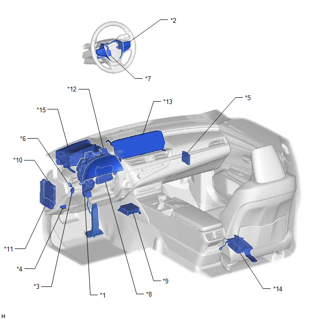
| *1 | ACCELERATOR PEDAL SENSOR | *2 | STEERING PAD SWITCH ASSEMBLY |
| *3 | STOP LIGHT SWITCH ASSEMBLY | *4 | DLC3 |
| *5 | CLEARANCE WARNING ECU ASSEMBLY | *6 | NO. 1 CLEARANCE WARNING BUZZER |
| *7 | STEERING SENSOR | *8 | AIR CONDITIONING AMPLIFIER ASSEMBLY |
| *9 | AIRBAG SENSOR ASSEMBLY - YAW RATE AND ACCELERATION SENSOR | *10 | MAIN BODY ECU (MULTIPLEX NETWORK BODY ECU) |
| *11 | INSTRUMENT PANEL JUNCTION BLOCK ASSEMBLY - ECU-DCC NO. 1 FUSE - ECU-IG1 NO. 4 FUSE - ECU-IG1 NO. 2 FUSE | *12 | COMBINATION METER ASSEMBLY |
| *13 | MULTI-INFORMATION DISPLAY | *14 | PARKING ASSIST ECU (w/ Panoramic View Monitor System) |
| *15 | HEADUP DISPLAY (METER MIRROR SUB-ASSEMBLY) (w/ Headup Display System) | - | - |
READ NEXT:
 Precaution
PRECAUTION PRECAUTION FOR DISCONNECTING CABLE FROM NEGATIVE BATTERY TERMINAL NOTICE: When disconnecting the cable from the negative (-) battery terminal, initialize the following systems after the cab
Problem Symptoms Table
PROBLEM SYMPTOMS TABLE HINT:
Use the table below to help determine the cause of problem symptoms. If multiple suspected areas are listed, the potential causes of the symptoms are listed in order of
System Description
SYSTEM DESCRIPTION FUNCTION OF COMPONENTS (a) The parking support brake system consists of the following components: Component Function Clearance Warning ECU Assembly
Sends the drive for
SEE MORE:
Fail-safe Chart
FAIL-SAFE CHART PULSE FAILURE (a) If a pulse sensor built into the power window regulator motor assembly malfunctions, the following power window operations will be prohibited. Multiplex Network Master Switch Assembly, Power Window Regulator Switch Assembly, Rear Power Window Regulator Switch Assemb
Do-it-yourself service precautions
If you perform maintenance by
yourself, be sure to follow the correct
procedure as given in these
sections.
Maintenance
Items
Parts and tools
12-volt battery
condition
Grease
Conventional wrench
(for terminal clamp
bolts)
Brake flui
