Lexus ES: Components
COMPONENTS
ILLUSTRATION
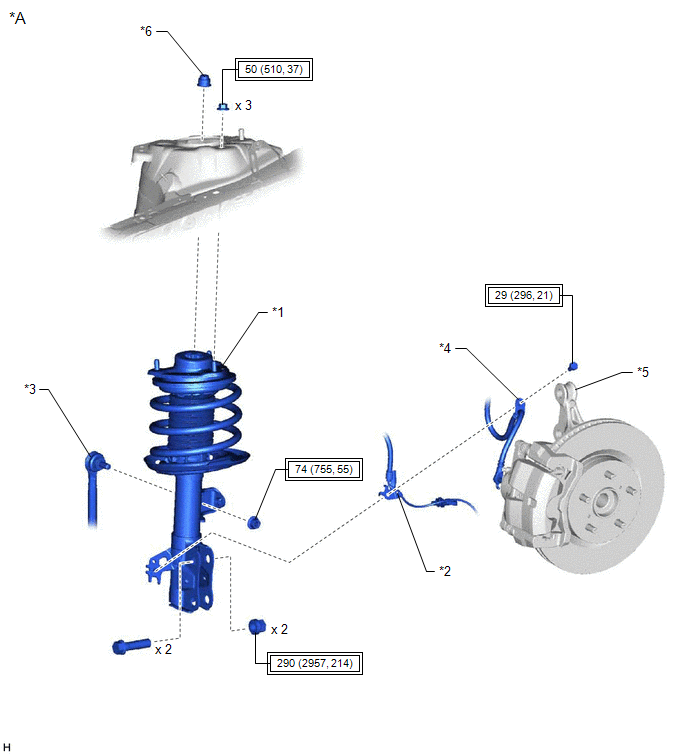
| *A | w/o AVS | - | - |
| *1 | FRONT SHOCK ABSORBER WITH COIL SPRING | *2 | FRONT SPEED SENSOR |
| *3 | FRONT STABILIZER LINK ASSEMBLY | *4 | FRONT FLEXIBLE HOSE |
| *5 | STEERING KNUCKLE | *6 | FRONT SHOCK ABSORBER LOCK NUT CAP |
.png) | Tightening torque for "Major areas involving basic vehicle performance such as moving/turning/stopping": N*m (kgf*cm, ft.*lbf) | - | - |
ILLUSTRATION
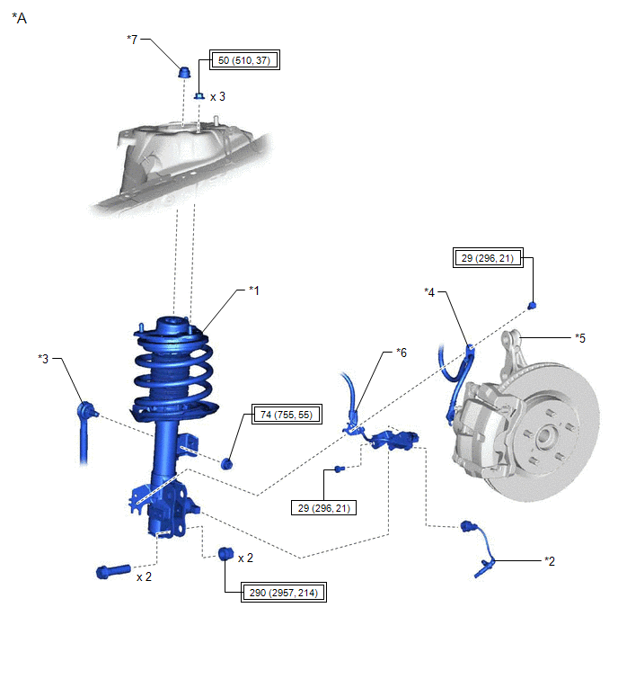
| *A | w/ AVS | - | - |
| *1 | FRONT SHOCK ABSORBER WITH COIL SPRING | *2 | FRONT SPEED SENSOR |
| *3 | FRONT STABILIZER LINK ASSEMBLY | *4 | FRONT FLEXIBLE HOSE |
| *5 | STEERING KNUCKLE | *6 | FRONT SPEED SENSOR WIRE |
| *7 | FRONT SHOCK ABSORBER LOCK NUT CAP | - | - |
| | Tightening torque for "Major areas involving basic vehicle performance such as moving/turning/stopping": N*m (kgf*cm, ft.*lbf) | .png) | N*m (kgf*cm, ft.*lbf): Specified torque |
ILLUSTRATION
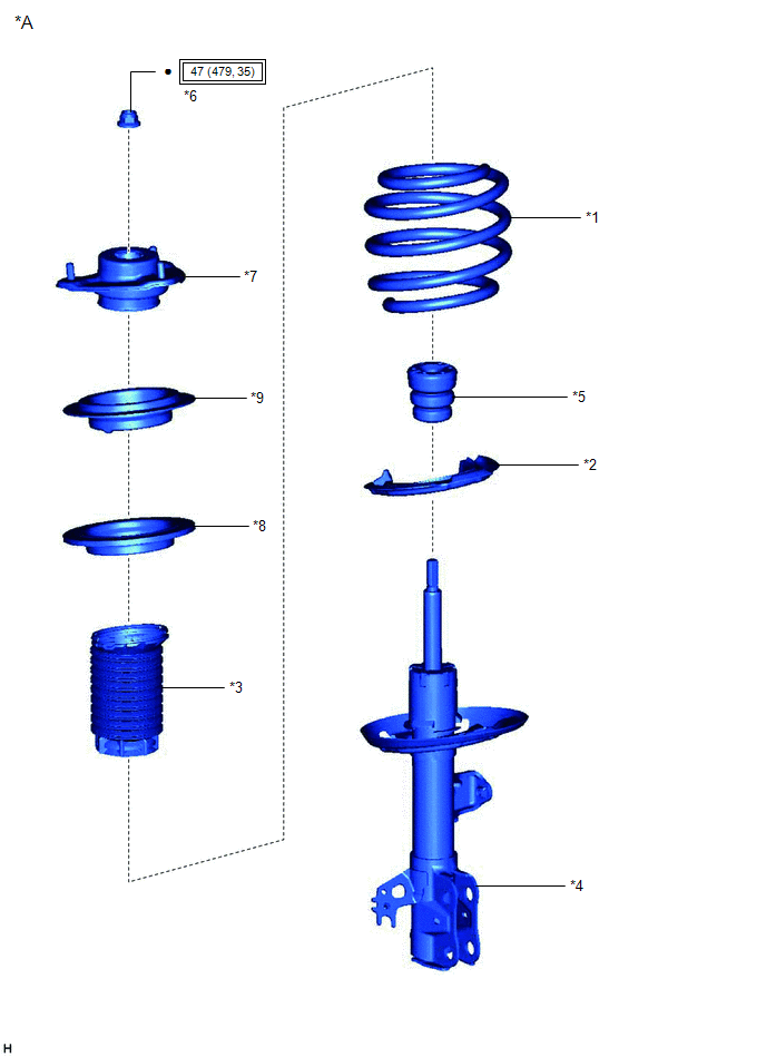
| *A | w/o AVS | - | - |
| *1 | FRONT COIL SPRING | *2 | FRONT LOWER COIL SPRING INSULATOR |
| *3 | FRONT NO. 1 SHOCK ABSORBER DUST COVER | *4 | FRONT SHOCK ABSORBER ASSEMBLY |
| *5 | FRONT SPRING BUMPER | *6 | FRONT SUPPORT TO FRONT SHOCK ABSORBER NUT |
| *7 | FRONT SUSPENSION SUPPORT SUB-ASSEMBLY | *8 | FRONT UPPER COIL SPRING INSULATOR |
| *9 | STRUT MOUNTING BEARING | - | - |
| | Tightening torque for "Major areas involving basic vehicle performance such as moving/turning/stopping": N*m (kgf*cm, ft.*lbf) | | N*m (kgf*cm, ft.*lbf): Specified torque |
| ● | Non-reusable part | - | - |
ILLUSTRATION
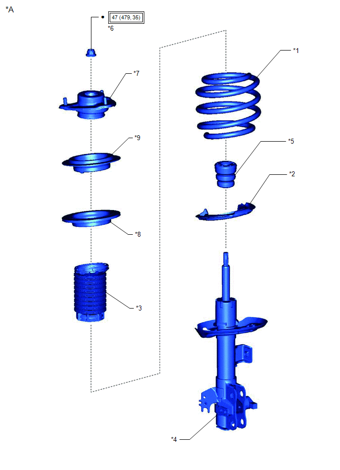
| *A | w/ AVS | - | - |
| *1 | FRONT COIL SPRING | *2 | FRONT LOWER COIL SPRING INSULATOR |
| *3 | FRONT NO. 1 SHOCK ABSORBER DUST COVER | *4 | FRONT SHOCK ABSORBER ASSEMBLY |
| *5 | FRONT SPRING BUMPER | *6 | FRONT SUPPORT TO FRONT SHOCK ABSORBER NUT |
| *7 | FRONT SUSPENSION SUPPORT SUB-ASSEMBLY | *8 | FRONT UPPER COIL SPRING INSULATOR |
| *9 | STRUT MOUNTING BEARING | - | - |
| | Tightening torque for "Major areas involving basic vehicle performance such as moving/turning/stopping": N*m (kgf*cm, ft.*lbf) | | N*m (kgf*cm, ft.*lbf): Specified torque |
| ● | Non-reusable part | - | - |
READ NEXT:
 Removal
REMOVAL CAUTION / NOTICE / HINT The necessary procedures (adjustment, calibration, initialization, or registration) that must be performed after parts are removed and installed, or replaced during fro
Inspection
INSPECTION PROCEDURE 1. INSPECT FRONT SHOCK ABSORBER ASSEMBLY (a) Compress and extend the front shock absorber assembly rod 4 times or more. Standard: When compressed and extended at a constant speed
Installation
INSTALLATION CAUTION / NOTICE / HINT HINT:
Use the same procedure for the RH side and LH side.
The following procedure is for the LH side.
PROCEDURE 1. INSTALL SST (w/o AVS) (a) Align the slot
SEE MORE:
Parts Location
PARTS LOCATION ILLUSTRATION *1 FRONT DOOR COURTESY LIGHT SWITCH ASSEMBLY (for LH) *2 FRONT DOOR COURTESY LIGHT SWITCH ASSEMBLY (for RH) *3 ROOF SUNSHADE ECU (SLIDING ROOF DRIVE GEAR ASSEMBLY) *4 SLIDING ROOF ECU (SLIDING ROOF DRIVE GEAR ASSEMBLY) *5 COMBINATION METER ASSEMB
Cornering Light Circuit
DESCRIPTION The headlight ECU sub-assembly controls the cornering lights. WIRING DIAGRAM except Bulb Type Turn Signal Light (for TMMK Made) for Bulb Type Turn Signal Light (for TMMK Made) CAUTION / NOTICE / HINT NOTICE:
If the headlight ECU sub-assembly LH has been replaced, it is necessary to
