Lexus ES: On-vehicle Inspection
ON-VEHICLE INSPECTION
PROCEDURE
1. INSPECT RAIN SENSOR
| (a) Disconnect the rain sensor connector. |
|
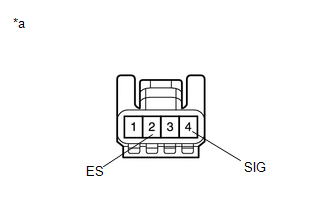
(b) Measure the voltage according to the value(s) in the table below.
Standard Voltage:
| Tester Connection | Condition | Specified Condition |
|---|---|---|
| 4 (SIG) - 2 (ES) | Engine switch on (IG) | 11 to 14 V |
(c) Measure the resistance according to the value(s) in the table below.
Standard Resistance:
| Tester Connection | Condition | Specified Condition |
|---|---|---|
| 2 (ES) - Body ground | Always | Below 1 Ω |
HINT:
If the result is not as specified, replace the rain sensor.
| (d) Reconnect the rain sensor connector. |
|

(e) Connect an oscilloscope to terminal 3 (MPX) and 2 (ES) of the rain sensor connector.
(f) Check for pulses according to the value(s) in the table below.
OK:
| Tester Connection | Condition | Specified Condition |
|---|---|---|
| 3 (MPX) - 2 (ES) | Engine switch on (IG) Front wiper switch in auto | Pulse generation |
HINT:
If the result is not as specified, replace the rain sensor.
READ NEXT:
 Removal
REMOVAL PROCEDURE 1. REMOVE RAIN SENSOR COVER *a Stopper Remove in this Direction (1) Remove in this Direction (2) (a) Release the stopper by pulling it out and disconnect the r
Installation
INSTALLATION PROCEDURE 1. INSTALL RAIN SENSOR TAPE HINT: The rain sensor tape is reusable. Only replace the tape if it is damaged or contaminated with foreign matter. (a) Clean the sensing portion of
Relay
On-vehicle InspectionON-VEHICLE INSPECTION PROCEDURE 1. INSPECT WIPER RELAY (a) Measure the resistance according to the value(s) in the table below. Standard Resistance: Tester Connection Co
SEE MORE:
Hybrid Vehicle Control ECU Communication Stop Mode
DESCRIPTION Detection Item Symptom Trouble Area Hybrid Vehicle Control ECU Communication Stop Mode Any of the following conditions are met:
Communication stop for "Hybrid Vehicle Control" is indicated on the "Communication Bus Check" screen of the Techstream.
Click here
Communic
Diagnosis System
DIAGNOSIS SYSTEM DIAGNOSIS FUNCTION (a) The diagnosis function turns off the cruise control indicator, illuminates the master warning light and displays a warning message when a malfunction is detected. When a malfunction is detected in the dynamic radar cruise control system, DTCs are stored in the
