Lexus ES: Installation
INSTALLATION
PROCEDURE
1. INSTALL RAIN SENSOR TAPE
HINT:
The rain sensor tape is reusable. Only replace the tape if it is damaged or contaminated with foreign matter.
(a) Clean the sensing portion of the rain sensor with a piece of cloth.
(b) Peel off the smaller release sheet, and then attach the rain sensor tape to the sensing portion of the rain sensor as shown in the illustration.
.png) | Rain Sensor Tape |
HINT:
Use your fingers to push out any air bubbles from under the tape.
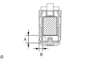
Standard Clearance| Area | Measurement |
|---|---|
| A | 14.4 mm (0.567 in.) |
| B | 7.25 mm (0.285 in.) |
2. INSTALL RAIN SENSOR
(a) Clean the windshield glass with a piece of cloth.
NOTICE:
- Make sure that there is no rain sensor tape residue remaining on the windshield glass. If there is, remove the residue.
- If there is any rain sensor tape residue remaining on the windshield glass, replace the tape.
(b) When installing a new rain sensor or when the rain sensor tape has been replaced:
(1) Peel off the release sheet.
HINT:
Do not touch the rain sensor tape surfaces.
(c) Connect the connector.
(d) Gradually attach the rain sensor to the windshield glass surface in the direction indicated by the arrow (1) shown in the illustration to prevent air bubbles from forming between them.
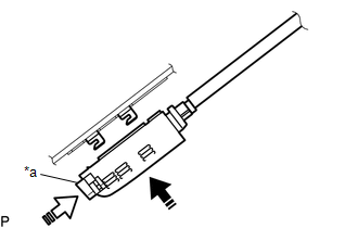
| *a | Stopper |
.png) | Install in this Direction (1) |
.png) | Install in this Direction (2) |
HINT:
Do not touch the rain sensor tape surface or windshield glass surface.
(e) Push in the stopper in the direction indicated by the arrow (2) shown in the illustration to install the rain sensor.
3. INSTALL RAIN SENSOR COVER
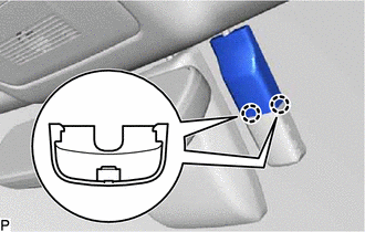
| (a) Engage the 2 claws and guide to install the rain sensor cover. |
|
READ NEXT:
 Relay
Relay
On-vehicle InspectionON-VEHICLE INSPECTION PROCEDURE 1. INSPECT WIPER RELAY (a) Measure the resistance according to the value(s) in the table below. Standard Resistance: Tester Connection Co
Components
COMPONENTS ILLUSTRATION *1 LEVEL WARNING SWITCH ASSEMBLY - -
SEE MORE:
Camshaft Position "A" - Timing Over-Advanced or System Performance Bank 1 Mechanical Failure (P001107,P002107)
DESCRIPTION Refer to DTC P001013. Click here DTC No. Detection Item DTC Detection Condition Trouble Area MIL Memory Note P001107 Camshaft Position "A" - Timing Over-Advanced or System Performance Bank 1 Mechanical Failure 10° CA or greater camshaft timing gear assembly (ban
Components
COMPONENTS ILLUSTRATION *1 AIR CLEANER ASSEMBLY WITH AIR CLEANER HOSE *2 COOL AIR INTAKE DUCT SEAL *3 ECM *4 INLET AIR CLEANER ASSEMBLY *5 NO. 1 ECM BRACKET *6 NO. 2 ECM BRACKET *7 VACUUM HOSE *8 NO. 1 FUEL VAPOR FEED HOSE *9 NO. 2 VENTILATION HOSE -
