Lexus ES: Terminals Of Ecu
TERMINALS OF ECU
REAR TELEVISION CAMERA ASSEMBLY
(a) Disconnect the T1 rear television camera assembly connector.

(b) Measure the voltage on the wire harness side connector according to the value(s) in the table below.
| Terminal No. (Symbol) | Wiring Color | Terminal Description | Condition | Specified Condition |
|---|---|---|---|---|
| T1-6 (CB+) - Body ground | GR - Body ground | Power source | Engine switch on (ACC) | 5.5 to 7.05 V |
If the result is not as specified, there may be a malfunction on the wire harness side.
(c) Reconnect the T1 rear television camera assembly connector.
(d) Check for pulses between each terminal of the connector.
| Terminal No. (Symbol) | Wiring Color | Terminal Description | Condition | Specified Condition |
|---|---|---|---|---|
| T1-3 (CV+) - T1-2 (CV-) | B - G | Video signal | Engine switch on (IG) Shift lever in R Camera lens not covered, displaying image | Pulse generation (Refer to waveform 1) |
| Engine switch on (IG) Shift lever in R Camera lens covered, blacking out screen | Pulse generation (Refer to waveform 2) | |||
| T1-5 (CGND) - Body ground | BR - Body ground | Camera ground | Always | Below 1 V |
HINT:
A waterproof connector is used for the rear television camera assembly. Therefore, inspect the waveform at the multi-display assembly with the connector connected.
If the result is not as specified, the rear television camera assembly may be malfunctioning.
(e) Reference (Oscilloscope waveform):
.png)
| *a | Waveform 1 (camera lens is not covered, displaying an image) |
| *b | Waveform 2 (camera lens is covered, blacking out the screen) |
| *c | Synchronization Signal |
| *d | Video Waveform |
HINT:
A waterproof connector is used for the rear television camera assembly. Therefore, inspect the waveform at the multi-display assembly with the connector connected.
(1) Waveform 1 (camera lens is not covered, displaying an image)
| Item | Content |
|---|---|
| Measurement terminal | T1-3 (CV+) - T1-2 (CV-) |
| Measurement setting | 200 mV/DIV., 50 μs./DIV. |
| Condition | Engine switch on (IG), shift lever in R |
HINT:
- The video waveform changes according to the image sent by the rear television camera assembly.
- The video waveform is constantly output when the engine switch is on (ACC).
(2) Waveform 2 (camera lens is covered, blacking out the screen)
| Item | Content |
|---|---|
| Measurement terminal | T1-3 (CV+) - T1-2 (CV-) |
| Measurement setting | 200 mV/DIV., 50 μs./DIV. |
| Condition | Engine switch on (IG), shift lever in R |
HINT:
- The video waveform changes according to the image sent by the rear television camera assembly.
- The video waveform is constantly output when the engine switch is on (ACC).
MULTI-DISPLAY ASSEMBLY
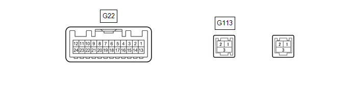
| Terminal No. (Symbol) | Wiring Color | Terminal Description | Condition | Specified Condition |
|---|---|---|---|---|
| G22-3 (REV) - G22-13 (GND1) | P - LA | Reverse signal | Engine running, shift lever not in R → in R | 3.5 V or higher → Below 1 V |
| G22-8 (V+) - G22-13 (GND1) | B - LA | Video signal | Engine switch on (IG) Shift lever in R Camera lens not covered, displaying image | Pulse generation (Refer to waveform 1) |
| Engine switch on (IG) Shift lever in R Camera lens covered, blacking out screen | Pulse generation (Refer to waveform 2) | |||
| G22-9 (V-) - G22-13 (GND1) | W - LA | Ground | Always | Below 1 V |
| G22-10 (CA+) - G22-21 (CGND) | R - G | Television camera assembly power supply | Engine switch on (ACC) | 5.5 to 7.05 V |
| G22-14 (CSWA) - G22-13(GND1)* | P - LA | Camera image change signal | Engine running Parking support alert (static objects) image not being displayed → Parking support alert (static objects) image being displayed | 3.5 V or higher → Below 1 V |
| G22-20 (CSLD) - Body ground | Shielded - Body ground | Shield ground | Always | Below 1 Ω |
| G22-21 (CGND) - Body ground | G - Body ground | Camera ground | Always | Below 1 Ω |
| G113-3 (GND) | Shielded | Shield ground | - | - |
- *: w/ Parking Support Alert System
(a) Reference (Oscilloscope waveform):
(1) Waveform 1 (camera lens not covered, displaying an image)
| Item | Content |
|---|---|
| Measurement terminal | G22-8 (V+) - G22-13 (GND1) |
| Measurement setting | 200 mV/DIV., 50 μs/DIV. |
| Condition | Engine switch on (IG), shift lever in R |
HINT:
- The video waveform changes according to the image sent by the rear television camera assembly.
- The video waveform is constantly output when the engine switch is on (ACC).
| *a | Waveform 1 (camera lens is not covered, displaying an image) |
| *b | Waveform 2 (camera lens is covered, blacking out the screen) |
| *c | Synchronization Signal |
| *d | Video Waveform |
(2) Waveform 2 (camera lens covered, blacking out the screen)
| Item | Content |
|---|---|
| Measurement terminal | G22-8 (V+) - G22-13 (GND1) |
| Measurement setting | 200 mV/DIV., 50 μs/DIV. |
| Condition | Engine switch on (IG), shift lever in R |
HINT:
- The video waveform changes according to the image sent by the rear television camera assembly.
- The video waveform is constantly output when the engine switch is on (ACC).
CLEARANCE WARNING ECU (w/ Parking Support Alert System)
Click here .gif)
READ NEXT:
 Lost Communication with ECM / PCM "A" (U0100,U0126,U0140,U0163,U0233,U1110)
DESCRIPTION These DTCs are stored if there is a malfunction in the CAN communication system connected to the rear television camera assembly. HINT: If CAN communication system DTCs are stored, they ma
CAN Communication Failure (Message Registry) (U1000)
DESCRIPTION This DTC is stored when the rear television camera assembly judges that it has an internal CAN malfunction. DTC No. Detection Item DTC Detection Condition Trouble Area U1000
SEE MORE:
Initialization
INITIALIZATION RESET BACK-UP BATTERY CONDITION HINT: If the back-up battery (mobilephone battery) has been replaced, it is necessary to perform the Reset Backup Battery Condition procedure. (a) Connect the Techstream to the DLC3. (b) Turn the power switch on (IG). (c) Turn the Techstream on. (d) Cho
Rear Right Center Sensor Malfunction (C1AE8)
DESCRIPTION The rear center ultrasonic sensor RH is installed to the rear bumper. The clearance warning ECU assembly detects obstacles based on signals received from the rear center ultrasonic sensor RH. If the rear center ultrasonic sensor RH has an open circuit or other malfunction, it will not fu
