Lexus ES: On-vehicle Inspection
ON-VEHICLE INSPECTION
CAUTION / NOTICE / HINT
HINT:
- Use the same procedure for the RH side and LH side.
- The following procedure is for the LH side.
PROCEDURE
1. REMOVE REAR WHEEL
Click here .gif)
2. DISCONNECT NO. 2 PARKING BRAKE WIRE ASSEMBLY
Click here
3. SEPARATE REAR DISC BRAKE CALIPER ASSEMBLY
Click here
4. REMOVE REAR DISC
Click here
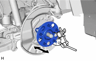
5. INSPECT REAR AXLE HUB BEARING LOOSENESS
| (a) Using a dial indicator with magnetic base, check for looseness near the center of the rear axle hub. Maximum Looseness: 0.05 mm (0.00196 in.) NOTICE:
HINT: If the looseness exceeds the maximum, replace the rear axle hub and bearing assembly. |
|
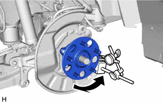
6. INSPECT REAR AXLE HUB RUNOUT
| (a) Using a dial indicator with magnetic base, check for runout on the surface of the rear axle hub outside the rear axle hub bolts. Maximum Runout: 0.05 mm (0.00196 in.) NOTICE:
HINT: If the runout exceeds the maximum, replace the rear axle hub and bearing assembly. |
|
7. INSTALL REAR DISC
Click here
8. INSTALL REAR DISC BRAKE CALIPER ASSEMBLY
Click here
9. CONNECT NO. 2 PARKING BRAKE WIRE ASSEMBLY
Click here
10. INSTALL REAR WHEEL
Click here
READ NEXT:
 Removal
REMOVAL CAUTION / NOTICE / HINT HINT:
Use the same procedure for the RH side and LH side.
The following procedure is for the LH side.
PROCEDURE 1. REMOVE REAR WHEEL Click here 2. REMOVE REAR
Components
COMPONENTS ILLUSTRATION *1 NO. 2 PARKING BRAKE WIRE ASSEMBLY *2 REAR AXLE HUB BOLT *3 REAR DISC *4 REAR DISC BRAKE CALIPER ASSEMBLY *5 REAR FLEXIBLE HOSE - - Tight
SEE MORE:
Generator Execution Torque Performance (P0E7100)
DTC SUMMARY MALFUNCTION DESCRIPTION This DTC indicates that the generator torque execution value does not correspond to the torque command value from the hybrid vehicle control ECU to the generator (MG1). The cause of this malfunction may be one of the following: Area Main Malfunction Descripti
Components
COMPONENTS ILLUSTRATION *A for Type A - - *1 FUEL SENDER GAUGE ASSEMBLY *2 FUEL SUCTION TUBE WITH PUMP AND GAUGE ASSEMBLY ILLUSTRATION *A for Type B - - *1 FUEL SENDER GAUGE ASSEMBLY *2 FUEL SUCTION TUBE WITH PUMP AND GAUGE ASSEMBLY *3 FUEL GAUGE BRAC
