Lexus ES: On-vehicle Inspection
ON-VEHICLE INSPECTION
PROCEDURE
1. INSPECT BRAKE BOOSTER ASSEMBLY
(a) Airtightness check
| (1) Start the engine and stop it after 1 or 2 minutes. Slowly depress the brake pedal several times. HINT: If the brake pedal can be depressed nearly to the floor the first time, but on the 2nd and 3rd time cannot be depressed as far, the brake booster assembly is airtight. |
|
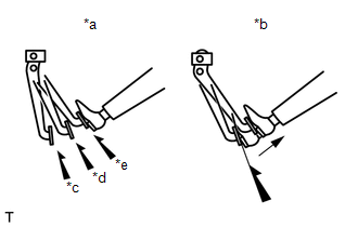
(2) Depress the brake pedal with the engine running, and stop the engine with the brake pedal depressed.
HINT:
If there is no change in the brake pedal reserve distance while holding the brake pedal depressed for 30 seconds, the brake booster assembly is airtight.
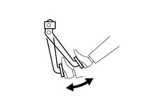
(b) Operation check
| (1) Depress the brake pedal several times with the engine switch off and check that there is no change in the brake pedal reserve distance when the brake pedal is depressed. |
|
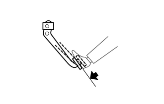
| (2) Depress and hold the brake pedal, then start the engine. HINT: If the brake pedal goes down slightly, operation is normal. |
|
READ NEXT:
 Reassembly
REASSEMBLY PROCEDURE 1. INSTALL VACUUM WARNING SWITCH ASSEMBLY (a) Install a new check valve grommet to the brake booster assembly. (b) Install the vacuum warning switch assembly to the brake booster
Removal
REMOVAL CAUTION / NOTICE / HINT The necessary procedures (adjustment, calibration, initialization or registration) that must be performed after parts are removed and installed, or replaced during brak
SEE MORE:
Destination Information Undefined (C1AB8)
DESCRIPTION This DTC is stored when correct destination information is not sent from the main body ECU (multiplex network body ECU) and destination information cannot be confirmed after a blind spot monitor sensor has been replaced. Blind Spot Monitor Master DTC No. Detection Item DTC Detecti
Radio Receiver Power Source Circuit
DESCRIPTION This is the power source circuit to operate the radio receiver assembly. WIRING DIAGRAM CAUTION / NOTICE / HINT NOTICE: Inspect the fuses for circuits related to this system before performing the following procedure. PROCEDURE 1. CHECK HARNESS AND CONNECTOR (RADIO RECEIVER ASSEMBL
