Lexus ES: Removal
REMOVAL
CAUTION / NOTICE / HINT
The necessary procedures (adjustment, calibration, initialization or registration) that must be performed after parts are removed and installed, or replaced during brake booster assembly removal/installation are shown below.
Necessary Procedures After Parts Removed/Installed/Replaced (for Gasoline Model:)| Replaced Part or Performed Procedure | Necessary Procedure | Effect/Inoperative Function when Necessary Procedure not Performed | Link |
|---|---|---|---|
|
*: When performing learning using the Techstream.
Click here | |||
| Battery terminal is disconnected/reconnected | Perform steering sensor zero point calibration | Lane Control System | |
| Pre-collision System | |||
| Parking Support Brake System* | |||
| Lighting System | |||
| Memorize steering angle neutral point | Parking Assist Monitor System | | |
| Panoramic View Monitor System | | ||
| Initialize power trunk lid system | Power Trunk Lid System | | |
NOTICE:
- After the engine switch is turned off, the radio receiver assembly records various types of memory and settings. As a result, after turning the engine switch off, make sure to wait at least 85 seconds before disconnecting the cable from the negative (-) battery terminal. (for Audio and Visual System)
- After the engine switch is turned off, the radio receiver assembly records various types of memory and settings. As a result, after turning the engine switch off, make sure to wait at least 85 seconds before disconnecting the cable from the negative (-) battery terminal. (for Navigation System)
CAUTION / NOTICE / HINT
NOTICE:
Make sure to release vacuum from the brake booster assembly before removing the brake master cylinder sub-assembly from the brake booster assembly.
PROCEDURE
1. PRECAUTION
NOTICE:
After turning the engine switch off, waiting time may be required before disconnecting the cable from the negative (-) battery terminal. Therefore, make sure to read the disconnecting the cable from the negative (-) battery terminal notices before proceeding with work.
2. REMOVE BRAKE MASTER CYLINDER SUB-ASSEMBLY
Click here .gif)
3. REMOVE NO. 1 INSTRUMENT PANEL UNDER COVER SUB-ASSEMBLY
Click here
4. REMOVE COWL TOP VENTILATOR LOUVER SUB-ASSEMBLY
Click here
5. REMOVE FRONT CENTER UPPER SUSPENSION BRACE SUB-ASSEMBLY
Click here
6. REMOVE AIR CLEANER ASSEMBLY WITH AIR CLEANER HOSE
Click here
7. REMOVE BATTERY CLAMP SUB-ASSEMBLY
| (a) Disengage the 5 clamps from the battery clamp sub-assembly. |
|
.png)
(b) Remove the 3 bolts, nut and battery clamp sub-assembly.
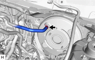
8. DISCONNECT UNION TO CHECK VALVE HOSE
| (a) Slide the clip and disconnect the union to check valve hose from the brake booster assembly. |
|
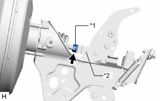
9. LOOSEN LOCK NUT
| (a) Loosen the lock nut of the brake master cylinder push rod clevis. |
|
10. REMOVE BRAKE PEDAL LINK PIN
Click here
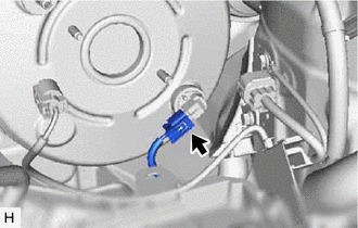
11. REMOVE BRAKE BOOSTER ASSEMBLY
| (a) Disconnect the connector from the vacuum warning switch assembly. |
|
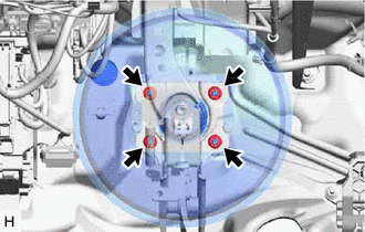
| (b) Remove the 4 nuts and push the brake booster assembly toward the engine compartment. NOTICE: Do not apply excessive force to the brake lines. |
|
(c) Remove the brake master cylinder push rod clevis and lock nut from the brake booster assembly.
(d) Remove the brake booster assembly from the vehicle body.
NOTICE:
Do not apply excessive force to the brake lines.
12. REMOVE BRAKE BOOSTER GASKET
READ NEXT:
 Components
COMPONENTS ILLUSTRATION *1 FRONT CENTER UPPER SUSPENSION BRACE SUB-ASSEMBLY - - Tightening torque for "Major areas involving basic vehicle performance such as moving/turning/stopping"
Installation
INSTALLATION PROCEDURE 1. INSTALL BRAKE MASTER CYLINDER GASKET (a) Install a new brake master cylinder gasket to the brake booster with master cylinder assembly. 2. INSTALL BRAKE BOOSTER WITH MASTER C
SEE MORE:
Removal
REMOVAL PROCEDURE 1. REMOVE FRONT DOOR SCUFF PLATE LH Click here 2. REMOVE COWL SIDE TRIM BOARD LH Click here 3. REMOVE FRONT DOOR OPENING TRIM COVER LH Click here 4. REMOVE INSTRUMENT SIDE PANEL LH Click here 5. REMOVE FRONT DOOR SCUFF PLATE RH HINT: Use the same procedure as for the LH sid
Inverter Low-voltage Circuit
DESCRIPTION The cause of the malfunction may be the low-voltage circuit. Check whether there is an open circuit in the inverter +B low-voltage power source system or a problem in the communication between the hybrid vehicle control ECU and inverter. Related Parts Check Area Inspection Inver
