Lexus ES: Luggage Compartment Door Closer Switch
Components
COMPONENTS
ILLUSTRATION
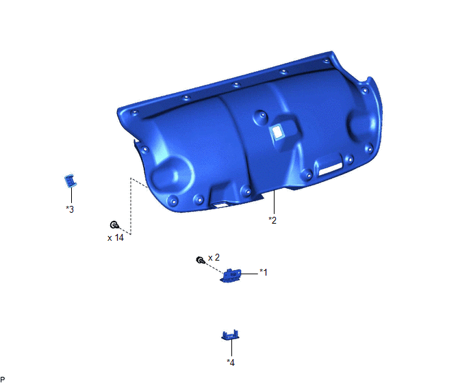
| *1 | DOOR CONTROL SWITCH | *2 | LUGGAGE COMPARTMENT DOOR COVER |
| *3 | LUGGAGE LOCK CONTROL CABLE PLATE | *4 | SWITCH BEZEL |
Removal
REMOVAL
PROCEDURE
1. REMOVE LUGGAGE LOCK CONTROL CABLE PLATE
Click here .gif)
2. REMOVE SWITCH BEZEL
Click here
3. REMOVE LUGGAGE COMPARTMENT DOOR COVER
Click here
4. REMOVE DOOR CONTROL SWITCH
| (a) Disconnect the connector. |
|
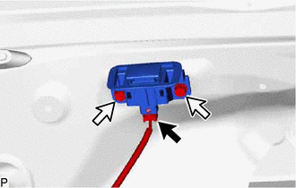
(b) Remove the 2 screws.
(c) Disengage the claw to remove the door control switch as shown in the illustration.

.png) | Remove in this Direction |
Inspection
INSPECTION
PROCEDURE
1. INSTALL DOOR CONTROL SWITCH
| (a) Check the resistance. (1) Measure the resistance according to the value(s) in the table below. Standard Resistance:
If the result is not as specified, replace the door control switch. |
|
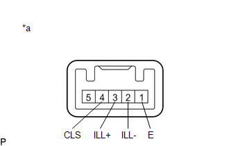
(b) Inspect the illumination operation.
(1) Apply auxiliary battery voltage to the switch connector and check that the door control switch illuminates.
OK:
| Tester Connection | Specified Condition |
|---|---|
| Auxiliary battery positive (+) → Terminal 3 (ILL+) Auxiliary battery negative (-) → Terminal 2 (ILL-) | Illumination illuminates |
If the result is not as specified, replace the door control switch.
Installation
INSTALLATION
PROCEDURE
1. INSTALL DOOR CONTROL SWITCH
(a) Engage the claw as shown in the illustration.
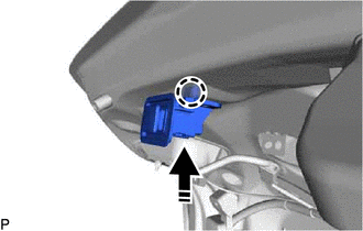
.png) | Install in this Direction |
(b) Install the door control switch with the 2 screws.
(c) Connect the connector.
2. INSTALL LUGGAGE COMPARTMENT DOOR COVER
Click here .gif)
3. INSTALL SWITCH BEZEL
Click here
4. INSTALL LUGGAGE LOCK CONTROL CABLE PLATE
Click here
READ NEXT:
 Components
COMPONENTS ILLUSTRATION *1 COWL SIDE TRIM BOARD LH *2 FRONT DOOR OPENING TRIM COVER LH *3 FRONT DOOR SCUFF PLATE LH *4 INSTRUMENT SIDE PANEL LH *5 LOWER INSTRUMENT PANEL FINI
Removal
REMOVAL PROCEDURE 1. REMOVE FRONT DOOR SCUFF PLATE LH Click here 2. REMOVE COWL SIDE TRIM BOARD LH Click here 3. REMOVE FRONT DOOR OPENING TRIM COVER LH Click here 4. REMOVE INSTRUMENT SIDE P
SEE MORE:
Components
COMPONENTS ILLUSTRATION *1 FRONT LOWER NO. 1 FLOOR HEAT INSULATOR - - N*m (kgf*cm, ft.*lbf): Specified torque - - ILLUSTRATION *1 PROPELLER WITH CENTER BEARING SHAFT ASSEMBLY *2 CENTER NO. 2 SUPPORT BEARING WASHER Tightening torque for "Major areas involving
Inverter Low-voltage Circuit
DESCRIPTION The cause of the malfunction may be the low-voltage circuit. Check whether there is an open circuit in the inverter +B low-voltage power source system or a problem in the communication between the hybrid vehicle control ECU and inverter. Related Parts Check Area Inspection Inver
