Lexus ES: Lost Communication with Humidity/Rain Sensor LIN (B1279)
DESCRIPTION
The main body ECU (multiplex network body ECU) and rain sensor communicate via LIN communication. The main body ECU (multiplex network body ECU) stores this DTC if communication becomes abnormal.
| DTC No. | Detection Item | DTC Detection Condition | Trouble Area | Memory | DTC Output from |
|---|---|---|---|---|---|
| B1279 | Lost Communication with Humidity/Rain Sensor LIN |
|
| ○ | Main Body |
WIRING DIAGRAM

CAUTION / NOTICE / HINT
NOTICE:
- Inspect the fuses of circuits related to this system before performing the following procedure.
-
Before replacing the main body ECU (multiplex network body ECU), refer to Registration.
Click here
.gif)
PROCEDURE
| 1. | CHECK FOR DTC |
(a) Connect the Techstream to the DLC3.
(b) Turn the engine switch on (IG).
(c) Turn the Techstream on.
(d) Enter the following menus: Body Electrical / Main Body / Trouble Codes.
(e) Check for DTCs.
Body Electrical > Main Body > Trouble Codes| Result | Proceed to |
|---|---|
| Only DTC B1279 is output | A |
| DTC B1279 and B1373 are output | B |
| B | .gif) | GO TO DTC B1373 |
|
.gif)
| 2. | CHECK HARNESS AND CONNECTOR (MAIN BODY ECU (MULTIPLEX NETWORK BODY ECU) - RAIN SENSOR) |
(a) Disconnect the G36 main body ECU (multiplex network body ECU) connector.
(b) Disconnect the P2 rain sensor connector.
(c) Measure the resistance according to the value(s) in the table below.
Standard Resistance:
| Tester Connection | Condition | Specified Condition |
|---|---|---|
| G36-3 (LIN3) - P2-3 (MPX) | Always | Below 1 Ω |
| NG | | REPAIR OR REPLACE HARNESS OR CONNECTOR |
|
| 3. | CHECK MAIN BODY ECU (MULTIPLEX NETWORK BODY ECU) |

| *a | Component without harness connected (Main Body ECU (Multiplex Network Body ECU) |
(a) Check for voltage and pulses according to the value(s) in the table below.
Standard Voltage:
| Tester Connection | Condition | Specified Condition |
|---|---|---|
| G36-3 (LIN3) - Body ground | Engine switch off | Below 1 V |
| Engine switch on (IG) | Pulse generation |
| NG | | REPLACE MAIN BODY ECU (MULTIPLEX NETWORK BODY ECU) |
|
| 4. | CHECK HARNESS AND CONNECTOR (POWER SOURCE - RAIN SENSOR) |

| *a | Front view of wire harness connector (to Rain Sensor) |
(a) Measure the voltage according to the value(s) in the table below.
Standard Voltage:
| Tester Connection | Condition | Specified Condition |
|---|---|---|
| P2-4 (SIG) - Body ground | Engine switch off | Below 1 V |
| Engine switch on (IG) | 11 to 14 V |
| NG | | GO TO STEP 7 |
|
| 5. | CHECK HARNESS AND CONNECTOR (RAIN SENSOR - BODY GROUND) |
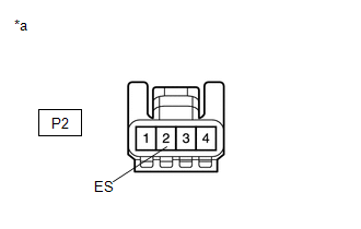
| *a | Front view of wire harness connector (to Rain Sensor) |
(a) Measure the resistance according to the value(s) in the table below.
Standard Resistance:
| Tester Connection | Condition | Specified Condition |
|---|---|---|
| P2-2 (ES) - Body ground | Always | Below 1 Ω |
| OK | | REPLACE RAIN SENSOR |
|
| 6. | INSPECT MAP LIGHT SUB-ASSEMBLY |
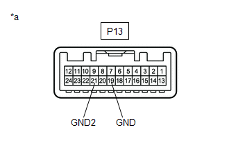
| *a | Component without harness connected (Map Light Sub-assembly) |
(a) Remove the map light sub-assembly.
Click here
(b) Measure the resistance according to the value(s) in the table below.
Standard Resistance:
| Tester Connection | Condition | Specified Condition |
|---|---|---|
| P13-19 (GND) - P13-21 (GND2) | Always | Below 1 Ω |
| OK | | REPAIR OR REPLACE HARNESS OR CONNECTOR |
| NG | | REPLACE MAP LIGHT SUB-ASSEMBLY |
| 7. | INSPECT MAP LIGHT SUB-ASSEMBLY |
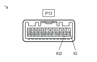
| *a | Component without harness connected (Map Light Sub-assembly) |
(a) Remove the map light sub-assembly.
Click here
(b) Measure the resistance according to the value(s) in the table below.
Standard Resistance:
| Tester Connection | Condition | Specified Condition |
|---|---|---|
| P13-1 (IG) - P13-14 (IG2) | Always | Below 1 Ω |
| OK | | REPAIR OR REPLACE HARNESS OR CONNECTOR |
| NG | | REPLACE MAP LIGHT SUB-ASSEMBLY |
READ NEXT:
 ECU Malfunction (B1370)
DESCRIPTION This DTC is stored when the windshield wiper motor assembly detects an internal malfunction. DTC No. Detection Item DTC Detection Condition Trouble Area Memory DTC Output from
Wiper Switch Signal Mismatch between LIN and Line (B1372)
DESCRIPTION Under normal operation, the windshield wiper motor assembly receives operation signals from the windshield wiper switch assembly via LIN communication. The windshield wiper motor assembly
Lost Communication with Wiper System LIN BUS (B1373)
DESCRIPTION The main body ECU (multiplex network body ECU) and windshield wiper motor assembly communicate via LIN communication. The main body ECU (multiplex network body ECU) stores this DTC if comm
SEE MORE:
Terminals Of Ecu
TERMINALS OF ECU CHECK SLIDING ROOF ECU (SLIDING ROOF DRIVE GEAR ASSEMBLY) (a) Disconnect the Q1 sliding roof ECU (sliding roof drive gear assembly) connector. (b) Measure the resistance and voltage according to the value(s) in the table below. HINT: Measure the values on the wire harness side with
Image from Camera for Panoramic View Monitor is Abnormal
DESCRIPTION The display signal from each camera is transmitted to the multi-display assembly via the parking assist ECU. WIRING DIAGRAM CAUTION / NOTICE / HINT NOTICE:
When "!" is displayed on the multi-display assembly after the cable is disconnected from the negative (-) battery terminal, cor
