Lexus ES: LIN Communication Bus Malfunction (B2325)
DESCRIPTION
If the main body ECU (multiplex network body ECU) detects a communication error with an ECU connected to the door bus lines for 8 seconds or more, DTC B2325 will be stored.
| DTC No. | Detection Item | DTC Detection Condition | Trouble Area |
|---|---|---|---|
| B2325 | LIN Communication Bus Malfunction | The main body ECU (multiplex network body ECU) detects a communication error with an ECU connected to the door bus lines for 8 seconds or more. |
|
- *: w/ Power Trunk Lid System
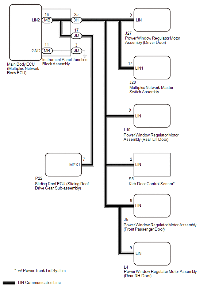
WIRING DIAGRAM
CAUTION / NOTICE / HINT
NOTICE:
-
When a power window regulator motor assembly is replaced or removed and reinstalled, it is necessary to perform initialization.
Click here
.gif)
-
When the sliding roof ECU (sliding roof drive gear sub-assembly) is replaced or removed and reinstalled, it is necessary to perform initialization.
Click here
-
Before replacing the main body ECU (multiplex network body ECU), refer to Registration.
Click here
PROCEDURE
| 1. | CHECK POWER WINDOW REGULATOR MOTOR ASSEMBLY (DRIVER DOOR) |
(a) Disconnect the J27 power window regulator motor assembly (driver door) connector.
(b) Clear the DTCs.
Body Electrical > Main Body > Clear DTCs(c) After 8 seconds have elapsed, check if the DTC is output.
Body Electrical > Main Body > Trouble Codes| Result | Proceed to |
|---|---|
| DTC B2325 is output | A |
| DTC B2325 is not output | B |
| B | .gif) | REPLACE POWER WINDOW REGULATOR MOTOR ASSEMBLY (DRIVER DOOR) |
|
.gif)
| 2. | CHECK MULTIPLEX NETWORK MASTER SWITCH ASSEMBLY |
(a) Disconnect the J20 multiplex network master switch assembly connector.
(b) Clear the DTCs.
Body Electrical > Main Body > Clear DTCs(c) After 10 seconds have elapsed, check if the DTC is output.
Body Electrical > Main Body > Trouble Codes| Result | Proceed to |
|---|---|
| DTC B2325 is output | A |
| DTC B2325 is not output | B |
| B | | REPLACE MULTIPLEX NETWORK MASTER SWITCH ASSEMBLY |
|
| 3. | CHECK POWER WINDOW REGULATOR MOTOR ASSEMBLY (FRONT PASSENGER DOOR) |
(a) Disconnect the J5 power window regulator motor assembly (front passenger door) connector.
(b) Clear the DTCs.
Body Electrical > Main Body > Clear DTCs(c) After 10 seconds have elapsed, check if the DTC is output.
Body Electrical > Main Body > Trouble Codes| Result | Proceed to |
|---|---|
| DTC B2325 is output | A |
| DTC B2325 is not output | B |
| B | | REPLACE POWER WINDOW REGULATOR MOTOR ASSEMBLY (FRONT PASSENGER DOOR) |
|
| 4. | CHECK POWER WINDOW REGULATOR MOTOR ASSEMBLY (REAR RH DOOR) |
(a) Disconnect the L4 power window regulator motor assembly (rear RH door) connector.
(b) Clear the DTCs.
Body Electrical > Main Body > Clear DTCs(c) After 10 seconds have elapsed, check if the DTC is output.
Body Electrical > Main Body > Trouble Codes| Result | Proceed to |
|---|---|
| DTC B2325 is output | A |
| DTC B2325 is not output | B |
| B | | REPLACE POWER WINDOW REGULATOR MOTOR ASSEMBLY (REAR RH DOOR) |
|
| 5. | CHECK POWER WINDOW REGULATOR MOTOR ASSEMBLY (REAR LH DOOR) |
(a) Disconnect the L10 power window regulator motor assembly (rear LH door) connector.
(b) Clear the DTCs.
Body Electrical > Main Body > Clear DTCs(c) After 10 seconds have elapsed, check if the DTC is output.
Body Electrical > Main Body > Trouble Codes| Result | Proceed to |
|---|---|
| DTC B2325 is output*1 | A |
| DTC B2325 is output*2 | B |
| DTC B2325 is not output | C |
- *1: w/ Power Trunk Lid System
- *2: w/o Power Trunk Lid System
| B | | GO TO STEP 7 |
| C | | REPLACE POWER WINDOW REGULATOR MOTOR ASSEMBLY (REAR LH DOOR) |
|
| 6. | CHECK KICK DOOR CONTROL SENSOR |
(a) Disconnect the S5 kick door control sensor connector.
(b) Clear the DTCs.
Body Electrical > Main Body > Clear DTCs(c) After 10 seconds have elapsed, check if the DTC is output.
Body Electrical > Main Body > Trouble Codes| Result | Proceed to |
|---|---|
| DTC B2325 is output | A |
| DTC B2325 is not output | B |
| B | | REPLACE KICK DOOR CONTROL SENSOR |
|
| 7. | CHECK SLIDING ROOF ECU (SLIDING ROOF DRIVE GEAR SUB-ASSEMBLY) |
(a) Disconnect the P22 sliding roof ECU (sliding roof drive gear sub-assembly) connector.
(b) Clear the DTCs.
Body Electrical > Main Body > Clear DTCs(c) After 10 seconds have elapsed, check if the DTC is output.
Body Electrical > Main Body > Trouble Codes| Result | Proceed to |
|---|---|
| DTC B2325 is output | A |
| DTC B2325 is not output | B |
| B | | REPLACE SLIDING ROOF ECU (SLIDING ROOF DRIVE GEAR SUB-ASSEMBLY) |
|
| 8. | CHECK HARNESS AND CONNECTOR (INSTRUMENT PANEL JUNCTION BLOCK ASSEMBLY - EACH ECU) |
(a) Disconnect the 3H instrument panel junction block assembly connector.
(b) Measure the resistance according to the value(s) in the table below.
Standard Resistance:
| Tester Connection | Condition | Specified Condition |
|---|---|---|
| 3H-25 - Body ground | Always | 10 kΩ or higher |
(c) Disconnect all other connectors in the same circuit.
(d) Measure the resistance according to the value(s) in the table below.
Standard Resistance:
| Tester Connection | Condition | Specified Condition |
|---|---|---|
| 3H-25 - Other terminals | Always | 10 kΩ or higher |
| NG | | REPAIR OR REPLACE HARNESS OR CONNECTOR |
|
| 9. | CHECK HARNESS AND CONNECTOR (INSTRUMENT PANEL JUNCTION BLOCK ASSEMBLY - SLIDING ROOF ECU (SLIDING ROOF DRIVE GEAR SUB-ASSEMBLY)) |
(a) Disconnect the 3D instrument panel junction block assembly connector.
(b) Measure the resistance according to the value(s) in the table below.
Standard Resistance:
| Tester Connection | Condition | Specified Condition |
|---|---|---|
| 3D-17 - Body ground | Always | 10 kΩ or higher |
| 3D-17 - Other terminals | Always | 10 kΩ or higher |
| NG | | REPAIR OR REPLACE HARNESS OR CONNECTOR |
|
| 10. | INSPECT INSTRUMENT PANEL JUNCTION BLOCK ASSEMBLY |
(a) Remove the instrument panel junction block assembly.
Click here
(b) Remove the main body ECU (multiplex network body ECU) from the instrument panel junction block assembly.
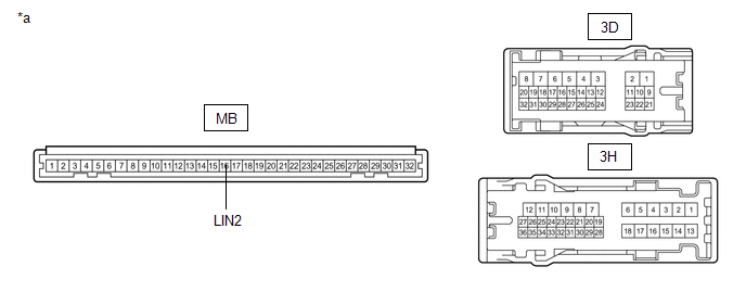
| *a | Component without harness connected (Instrument Panel Junction Block Assembly) | - | - |
(c) Measure the resistance according to the value(s) in the table below.
HINT:
This inspection is to check the LIN communication line in the instrument panel junction block assembly that connects the wire harness to the built-in main body ECU (multiplex network body ECU).
Standard Resistance:
| Tester Connection | Condition | Specified Condition |
|---|---|---|
| 3H-25 - 3D-3 | Always | 10 kΩ or higher |
| MB-16 (LIN2) - Other terminals | Always | 10 kΩ or higher |
| NG | | REPLACE INSTRUMENT PANEL JUNCTION BLOCK ASSEMBLY |
|
| 11. | INSPECT MAIN BODY ECU (MULTIPLEX NETWORK BODY ECU) |
(a) Install the main body ECU (multiplex network body ECU) to the instrument panel junction block assembly.
Click here
(b) Install the instrument panel junction block assembly.
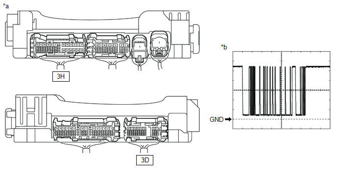
| *a | Component with harness connected (Instrument Panel Junction Block Assembly) | *b | Waveform |
(c) Using a Techstream, check the waveform.
HINT:
This inspection is to check the LIN communication line in the instrument panel junction block assembly that connects the wire harness to the built-in main body ECU (multiplex network body ECU).
OK:
| Tester Connection | Condition | Tool Setting | Specified Condition |
|---|---|---|---|
| 3H-25 - Body ground | Power switch on (IG) | 2 V/DIV., 200 ms/DIV. | Pulse generation (See waveform) |
| 3D-17 - Body ground | Power switch on (IG) | 2 V/DIV., 200 ms/DIV. | Pulse generation (See waveform) |
| OK | | USE SIMULATION METHOD TO CHECK |
| NG | | REPLACE MAIN BODY ECU (MULTIPLEX NETWORK BODY ECU) |
READ NEXT:
 P/W Master Switch Communication Stop (B1206,B1273,B2321-B2324)
DESCRIPTION This DTC is stored when LIN communication between the main body ECU (multiplex network body ECU) and multiplex network master switch assembly, sliding roof ECU (sliding roof drive gear sub
Diagnostic Trouble Code Chart
DIAGNOSTIC TROUBLE CODE CHART LIN Communication System DTC No. Detection Item Link B1206 P/W Master Switch Communication Stop B1273 Sliding Roof ECU Communication Stop
Data List / Active Test
DATA LIST / ACTIVE TEST DATA LIST HINT: Using the Techstream to read the Data List allows the values or states of switches, sensors, actuators and other items to be read without removing any parts. Th
SEE MORE:
Data List / Active Test
DATA LIST / ACTIVE TEST DATA LIST NOTICE: In the table below, the values listed under "Normal Condition" are reference values. Do not depend solely on these reference values when deciding whether a part is faulty or not. HINT: Using the Techstream to read the Data List allows the values or states of
Problem Symptoms Table
PROBLEM SYMPTOMS TABLE HINT:
Use the table below to help determine the cause of problem symptoms. If multiple suspected areas are listed, the potential causes of the symptoms are listed in order of probability in the "Suspected Area" column of the table. Check each symptom by checking the suspect
