Lexus ES: Left Front Wheel Speed Sensor Signal Stuck Low (C050023)
DESCRIPTION
Refer to DTC C050012
Click here .gif)
| DTC No. | Detection Item | DTC Detection Condition | Trouble Area |
|---|---|---|---|
| C050023 | Left Front Wheel Speed Sensor Signal Stuck Low |
|
|
| Vehicle Condition | ||||
|---|---|---|---|---|
| Pattern 1 | Pattern 2 | Pattern 3 | ||
| Diagnosis Condition | The vehicle is driven from 0 km/h to 12 km/h (0 mph to 7 mph). | ○ | - | - |
| The vehicle speed reaches 18 km/h (11 mph). | - | ○ | - | |
| The vehicle speed and wheel speed are both 50.4 km/h (31.3 mph) or more. | - | - | ○ | |
| Malfunction Status | The wheel speed is 1.8 km/h (1.1 mph) or less. | ○ | - | - |
| The wheel speed has not exceeded 1.8 km/h (1.1 mph). | - | ○ | - | |
| The pulse signal is not detected. | - | - | ○ | |
| Detection Time | 0.6 seconds or more. | - | 0.08 seconds or more. | |
| Number of Trips | 1 trip | 1 trip | 1 trip | |
HINT:
DTC will be output when conditions for either of the patterns in the table above are met.
CAUTION / NOTICE / HINT
NOTICE:
-
After replacing or removing and installing a speed sensor, perform Dealer Mode (Signal Check) inspection to confirm that the speed sensors are operating correctly.
Click here
-
DTC precaution
Click here
Procedure to clear warning lights (When not clearing DTCs) Procedure
- Repair or replacement.
- Turn the engine switch on (IG).
- Drive the vehicle at 2 km/h (1 mph) or more to clear the warning lights.
PROCEDURE
| 1. | CHECK FREEZE FRAME DATA (WHEEL SPEED) |
(a) Connect the Techstream to the DLC3.
(b) Turn the engine switch on (IG).
(c) Enter the following menus: Chassis / Brake/EPB / Trouble Codes.
(d) Select a DTC to display the Freeze Frame Data.
(e) Read the freeze frame data of DTC C050023.
Chassis > Brake/EPB| Tester Display | Measurement Item | Range | Normal Condition | Diagnostic Note |
|---|---|---|---|---|
| FR Wheel Speed | Front wheel speed sensor RH reading | Min.: 0.0 km/h (0 mph), Max.: 6553.5 km/h (4072 mph) | Vehicle stopped: 0.0 km/h (0.0 mph) | When driving at constant speed: No large fluctuations |
| FL Wheel Speed | Front wheel speed sensor LH reading | Min.: 0.0 km/h (0 mph), Max.: 6553.5 km/h (4072 mph) | Vehicle stopped: 0.0 km/h (0.0 mph) | When driving at constant speed: No large fluctuations |
| RR Wheel Speed | Rear wheel speed sensor RH reading | Min.: 0.0 km/h (0 mph), Max.: 6553.5 km/h (4072 mph) | Vehicle stopped: 0.0 km/h (0.0 mph) | When driving at constant speed: No large fluctuations |
| RL Wheel Speed | Rear wheel speed sensor LH reading | Min.: 0.0 km/h (0 mph), Max.: 6553.5 km/h (4072 mph) | Vehicle stopped: 0.0 km/h (0.0 mph) | When driving at constant speed: No large fluctuations |
| Tester Display |
|---|
| FR Wheel Speed |
| FL Wheel Speed |
| RR Wheel Speed |
| RL Wheel Speed |
| Result | Proceed to |
|---|---|
| The value of FL Wheel Speed is 2 km/h (1 mph) or less when all other values are 12 km/h (7 mph) or more. | A |
| The value of FL Wheel Speed is 2 km/h (1 mph) or less when all other values are 50 km/h (31 mph) or more. | B |
| B |  | GO TO STEP 3 |
|

| 2. | READ VALUE USING TECHSTREAM (FL WHEEL SPEED) |
(a) Connect the Techstream to the DLC3.
(b) Turn the engine switch on (IG).
(c) Enter the following menus: Chassis / Brake/EPB / Data List.
Chassis > Brake/EPB > Data List| Tester Display | Measurement Item | Range | Normal Condition | Diagnostic Note |
|---|---|---|---|---|
| FL Wheel Speed | Front wheel speed sensor LH reading | Min.: 0.0 km/h (0.0 mph), Max.: 6553.5 km/h (4072 mph) | Vehicle stopped: 0.0 km/h (0.0 mph) | When driving at constant speed: No large fluctuations |
| Tester Display |
|---|
| FL Wheel Speed |
(d) Start the engine and perform a road test.
(e) Check that the value of FL Wheel Speed changes in accordance with vehicle speed when accelerating from 0 km/h to 20 km/h (0 mph to 12 mph).
OK:
The value of FL Wheel Speed changes in accordance with vehicle speed.
HINT:
If the result of the road test is within the specified range, it is possible that this DTC was stored due to a particular situation such as brake drag, wheelspin or wheel lockup.
| OK | | USE SIMULATION METHOD TO CHECK |
|
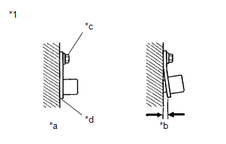
| 3. | CHECK FRONT SPEED SENSOR LH INSTALLATION |
| (a) Check the front speed sensor LH installation. OK: There is no clearance between the front speed sensor LH and the steering knuckle LH. The installation bolt is tightened properly. Torque 8.5 N*m (87 kgf*cm, 75 in.*lbf) |
|
| OK | | REPLACE FRONT SPEED SENSOR LH |
| NG | | REINSTALL OR REPLACE FRONT SPEED SENSOR LH |
READ NEXT:
 Left Front Wheel Speed Sensor Signal Stuck High (C050024)
DESCRIPTION Refer to DTC C050012 Click here DTC No. Detection Item DTC Detection Condition Trouble Area C050024 Left Front Wheel Speed Sensor Signal Stuck High The speed sensor sign
Left Front Wheel Speed Sensor Internal Electronic Failure (C050049)
DESCRIPTION When the system is starting up and the skid control ECU (brake actuator assembly) detects a speed sensor circuit malfunction via the speed sensor circuit self-diagnosis function, this DTC
Right Front Wheel Speed Sensor Circuit Short to Battery (C050612)
DESCRIPTION Each speed sensor detects wheel speed and sends signals to the skid control ECU (brake actuator assembly). These signals are used by the ABS control. The speed sensor detects the magnetic
SEE MORE:
ABS Operates Before Necessary When Braking
DESCRIPTION Troubleshooting for when ABS operates too soon due to a noisy signal from the speed sensor, a difference in output, etc. CAUTION / NOTICE / HINT NOTICE:
After replacing or removing and installing a speed sensor, perform Dealer Mode (Signal Check) inspection to confirm that the speed s
Components
COMPONENTS
ILLUSTRATION
*1
REAR FLEXIBLE HOSE
*2
GASKET
*3
UNION BOLT
*4
BRAKE LINE
Tightening torque for "Major areas involving basic vehicle performance
such as movi
