Lexus ES: Right Front Wheel Speed Sensor Circuit Short to Battery (C050612)
DESCRIPTION
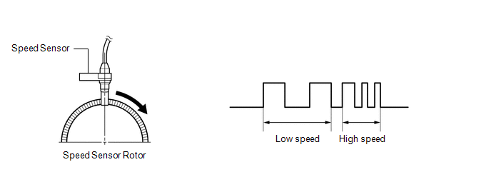
Each speed sensor detects wheel speed and sends signals to the skid control ECU (brake actuator assembly). These signals are used by the ABS control.
The speed sensor detects the magnetic fields of the speed sensor rotor as it rotates and outputs a pulse signal.
The frequency of the pulse varies in accordance with the rotational speed of the speed sensor rotor and the system uses this to determine the wheel speed.
HINT:
The following example shows a pulse signal that is output when the wire harness connectors are connected to the speed sensors and skid control ECU (brake actuator assembly).
| DTC No. | Detection Item | DTC Detection Condition | Trouble Area |
|---|---|---|---|
| C050612 | Right Front Wheel Speed Sensor Circuit Short to Battery | A short to +B in the speed sensor signal circuit is detected for 0.12 seconds or more. |
|
*: w/ AVS
WIRING DIAGRAM
w/o AVS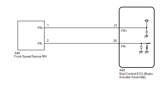 w/ AVS
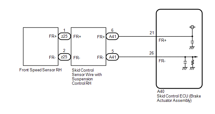
CAUTION / NOTICE / HINT
NOTICE:
-
After replacing the skid control ECU (brake actuator assembly), perform acceleration sensor zero point calibration and store system information memorization.
Click here
.gif)
-
After replacing or removing and installing a speed sensor, perform Dealer Mode (Signal Check) inspection to confirm that the speed sensors are operating correctly.
Click here
PROCEDURE
| 1. | CHECK VEHICLE |
(a) Check if the vehicle is equipped with AVS.
| Result | Proceed to |
|---|---|
| w/o AVS | A |
| w/ AVS | B |
| B |  | GO TO STEP 5 |
|

| 2. | CHECK HARNESS AND CONNECTOR (SENSOR GROUND CIRCUIT) |
| (a) Make sure that there is no looseness at the locking part and the connecting part of the connectors. OK: The connector is securely connected. |
|
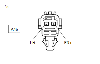
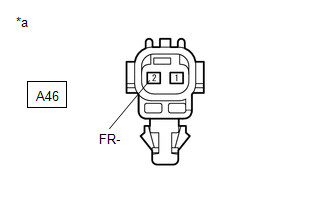
(b) Disconnect the A46 front speed sensor RH connector.
(c) Check both the connector case and the terminals for deformation and corrosion.
OK:
No deformation or corrosion.
(d) Turn the engine switch on (IG).
(e) Measure the voltage according to the value(s) in the table below.
Standard Voltage:
| Tester Connection | Condition | Specified Condition |
|---|---|---|
| A46-1 (FR+) - A46-2 (FR-) | Engine switch on (IG) | 11 to 14 V |
| OK | | REPLACE FRONT SPEED SENSOR RH |
|
| 3. | CHECK HARNESS AND CONNECTOR (FRONT SPEED SENSOR RH - BRAKE ACTUATOR ASSEMBLY) |
| (a) Make sure that there is no looseness at the locking part and the connecting part of the connectors. OK: The connector is securely connected. |
|
(b) Disconnect the A40 skid control ECU (brake actuator assembly) connector.
(c) Disconnect the A46 front speed sensor RH connector.
(d) Check both the connector case and the terminals for deformation and corrosion.
OK:
No deformation or corrosion.
(e) Measure the voltage according to the value(s) in the table below.
Standard Voltage:
| Tester Connection | Condition | Specified Condition |
|---|---|---|
| A46-2 (FR-) - Body ground | Always | Below 1.5 V |
| NG | | REPAIR OR REPLACE HARNESS OR CONNECTOR |
|
| 4. | CHECK HARNESS AND CONNECTOR (FRONT SPEED SENSOR RH - BRAKE ACTUATOR ASSEMBLY) |
(a) Make sure that there is no looseness at the locking part and the connecting part of the connectors.
OK:
The connector is securely connected.
(b) Disconnect the A40 skid control ECU (brake actuator assembly) connector.
(c) Disconnect the A46 front speed sensor RH connector.
(d) Check both the connector case and the terminals for deformation and corrosion.
OK:
No deformation or corrosion.
(e) Measure the resistance according to the value(s) in the table below.
Standard Resistance:
| Tester Connection | Condition | Specified Condition |
|---|---|---|
| A46-1 (FR+) or A40-21 (FR+) - A46-2 (FR-) or A40-26 (FR-) | Always | 10 kΩ or higher |
| OK | | REPLACE BRAKE ACTUATOR ASSEMBLY |
| NG | | REPAIR OR REPLACE HARNESS OR CONNECTOR |
| 5. | CHECK HARNESS AND CONNECTOR (SENSOR GROUND CIRCUIT) |
| (a) Make sure that there is no looseness at the locking part and the connecting part of the connectors. OK: The connector is securely connected. |
|
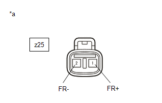
(b) Disconnect the z25 front speed sensor RH connector.
(c) Check both the connector case and the terminals for deformation and corrosion.
OK:
No deformation or corrosion.
(d) Turn the engine switch on (IG).
(e) Measure the voltage according to the value(s) in the table below.
Standard Voltage:
| Tester Connection | Condition | Specified Condition |
|---|---|---|
| z25-1 (FR+) - z25-2 (FR-) | Engine switch on (IG) | 11 to 14 V |
| OK | | REPLACE FRONT SPEED SENSOR RH |
|
| 6. | CHECK HARNESS AND CONNECTOR (SENSOR GROUND CIRCUIT) |
| (a) Make sure that there is no looseness at the locking part and the connecting part of the connectors. OK: The connector is securely connected. |
|
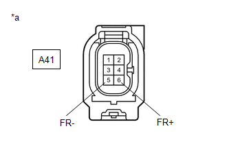
(b) Disconnect the A41 skid control sensor wire with suspension control RH connector.
(c) Check both the connector case and the terminals for deformation and corrosion.
OK:
No deformation or corrosion.
(d) Turn the engine switch on (IG).
(e) Measure the voltage according to the value(s) in the table below.
Standard Voltage:
| Tester Connection | Condition | Specified Condition |
|---|---|---|
| A41-6 (FR+) - A41-5 (FR-) | Engine switch on (IG) | 11 to 14 V |
| OK | | REPLACE SKID CONTROL SENSOR WIRE WITH SUSPENSION CONTROL RH |
|
| 7. | CHECK HARNESS AND CONNECTOR (SKID CONTROL SENSOR WIRE WITH SUSPENSION CONTROL RH - BRAKE ACTUATOR ASSEMBLY) |
| (a) Make sure that there is no looseness at the locking part and the connecting part of the connectors. OK: The connector is securely connected. |
|
(b) Disconnect the A40 skid control ECU (brake actuator assembly) connector.
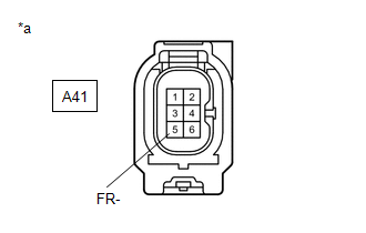
(c) Disconnect the A41 skid control sensor wire with suspension control RH connector.
(d) Check both the connector case and the terminals for deformation and corrosion.
OK:
No deformation or corrosion.
(e) Measure the voltage according to the value(s) in the table below.
Standard Voltage:
| Tester Connection | Condition | Specified Condition |
|---|---|---|
| A41-5 (FR-) - Body ground | Always | Below 1.5 V |
| NG | | REPAIR OR REPLACE HARNESS OR CONNECTOR |
|
| 8. | CHECK HARNESS AND CONNECTOR (SKID CONTROL SENSOR WIRE WITH SUSPENSION CONTROL RH - BRAKE ACTUATOR ASSEMBLY) |
(a) Make sure that there is no looseness at the locking part and the connecting part of the connectors.
OK:
The connector is securely connected.
(b) Disconnect the A40 skid control ECU (brake actuator assembly) connector.
(c) Disconnect the A41 skid control sensor wire with suspension control RH connector.
(d) Check both the connector case and the terminals for deformation and corrosion.
OK:
No deformation or corrosion.
(e) Measure the resistance according to the value(s) in the table below.
Standard Resistance:
| Tester Connection | Condition | Specified Condition |
|---|---|---|
| A41-6 (FR+) or A40-21 (FR+) - A41-5 (FR-) or A40-26 (FR-) | Always | 10 kΩ or higher |
| OK | | REPLACE BRAKE ACTUATOR ASSEMBLY |
| NG | | REPAIR OR REPLACE HARNESS OR CONNECTOR |
READ NEXT:
 Right Front Wheel Speed Sensor Circuit Short to Ground or Open (C050614)
DESCRIPTION Refer to DTC C050612 Click here DTC No. Detection Item DTC Detection Condition Trouble Area C050614 Right Front Wheel Speed Sensor Circuit Short to Ground or Open A shor
Right Front Wheel Speed Sensor Signal Stuck Low (C050623)
DESCRIPTION Refer to DTC C050612 Click here DTC No. Detection Item DTC Detection Condition Trouble Area C050623 Right Front Wheel Speed Sensor Signal Stuck Low
When the vehicle i
Right Front Wheel Speed Sensor Signal Stuck High (C050624)
DESCRIPTION Refer to DTC C050612 Click here DTC No. Detection Item DTC Detection Condition Trouble Area C050624 Right Front Wheel Speed Sensor Signal Stuck High The speed sensor sig
SEE MORE:
Inspection
INSPECTION PROCEDURE 1. INSPECT FUEL PUMP ASSEMBLY (a) Measure the resistance according to the value(s) in the table below. Standard Resistance: Tester Connection Condition Specified Condition 1 - 2 20°C (68°F) 0.45 to 0.55 Ω If the result is not as specified, replace the fu
Components
COMPONENTS ILLUSTRATION *1 VACUUM HOSE *2 FLOW SHUTTING VALVE (NO. 1 WATER BY-PASS HOSE) *3 WATER BY-PASS HOSE ASSEMBLY *4 STEERING GEAR HEAT INSULATOR *5 WIRE HARNESS *6 FRONT FRAME ASSEMBLY *7 TRANSMISSION BREATHER CLAMP *8 HOSE CLAMP Tightening torqu
