Lexus ES: Installation
INSTALLATION
PROCEDURE
1. INSTALL REMOTE OPERATION CONTROLLER ASSEMBLY
(a) Install the remote operation controller assembly with the 4 screws as shown in the illustration.
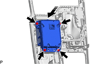
.png) | Install in this Direction |
2. INSTALL REAR UPPER CONSOLE PANEL SUB-ASSEMBLY
Click here .gif)
3. INSTALL SHIFT LEVER KNOB SUB-ASSEMBLY
for UA80E: Click here
for P710: Click here
4. INSTALL CENTER INSTRUMENT CLUSTER FINISH PANEL SUB-ASSEMBLY
Click here
5. INSTALL INSTRUMENT PANEL FINISH PANEL END RH
Click here
6. INSTALL INSTRUMENT PANEL FINISH PANEL END LH
Click here
READ NEXT:
 Installation
INSTALLATION PROCEDURE 1. INSTALL REMOTE OPERATION CONTROLLER ASSEMBLY (a) Install the remote operation controller assembly with the 4 screws as shown in the illustration. Install in this Direc
Removal
REMOVAL PROCEDURE 1. REMOVE INSTRUMENT PANEL FINISH PANEL END LH Click here 2. REMOVE INSTRUMENT PANEL FINISH PANEL END RH Click here 3. REMOVE CENTER INSTRUMENT CLUSTER FINISH PANEL SUB-ASSEMBLY
Removal
REMOVAL PROCEDURE 1. REMOVE INSTRUMENT PANEL FINISH PANEL END LH Click here 2. REMOVE INSTRUMENT PANEL FINISH PANEL END RH Click here 3. REMOVE CENTER INSTRUMENT CLUSTER FINISH PANEL SUB-ASSEMBLY
SEE MORE:
System Diagram
SYSTEM DIAGRAM Communication Table Transmitter Receiver Signal Communication Method Rear Window Defogger Switch (Air Conditioning Control Assembly) Air Conditioning Amplifier Assembly Rear Window Defogger Switch Signal LIN
Transmission (Input) Mechanical Linkage Failure (P1C8679)
DTC SUMMARY Refer to the DTC summary for DTC P1C7779. Click here DESCRIPTION Refer to the description for DTC P1C7779. Click here DTC No. Detection Item DTC Detection Condition Trouble Area MIL Warning Indicate P1C8679 Transmission (Input) Mechanical Linkage Failure Hybrid v
© 2016-2026 Copyright www.lexguide.net
