Lexus ES: Installation
INSTALLATION
CAUTION / NOTICE / HINT
HINT:
- Use the same procedure for the RH side and LH side.
- The following procedure is for the LH side.
PROCEDURE
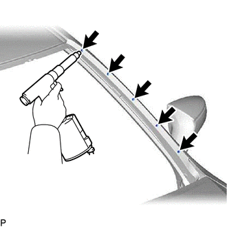
1. INSTALL NO. 3 WINDSHIELD OUTSIDE MOULDING CLIP
HINT:
Perform the following procedure only when replacement of a No. 3 windshield outside moulding clip is necessary.
(a) Using a riveter with a nose piece, install 5 new No. 3 windshield outside moulding clips.
HINT:
If the mandrel of the No. 3 windshield outside moulding clip does not come off on the first operation of the rivet gun, slide the rivet gun forward on the mandrel and operate it again.
NOTICE:
- Do not pry the No. 3 windshield outside moulding clip with the riveter, as this will cause damage to the riveter and mandrel.
-
Confirm that the No. 3 windshield outside moulding clips are seated properly against the vehicle body.
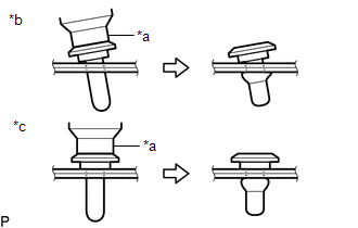
*a
Riveter
*b
Incorrect
*c
Correct
- Do not tilt the riveter when installing the No. 3 windshield outside moulding clip to the vehicle body.
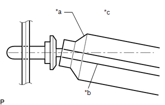
| *a | Riveter |
| *b | Mandrel |
| *c | Incorrect |
(b) Install the windshield glass sub-assembly.
Click here .gif)
2. INSTALL NO. 1 WINDSHIELD OUTSIDE MOULDING CLIP
HINT:
Perform the following procedure only when replacement of a No. 1 windshield outside moulding clip is necessary.
(a) Engage the 5 claws to install the 5 No. 1 windshield outside moulding clips as shown in the illustration.
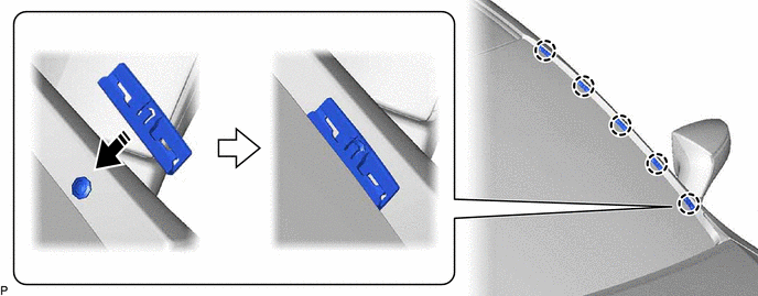
.png) | Install in this Direction | - | - |
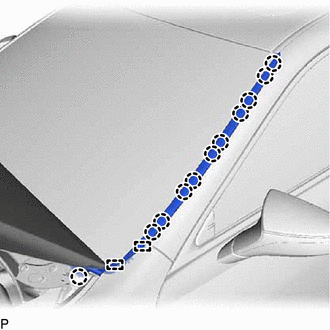
3. INSTALL WINDSHIELD OUTSIDE MOULDING
| (a) Engage the 11 claws and 2 guides to install the windshield outside moulding. |
|
READ NEXT:
 Horn
Horn
ComponentsCOMPONENTS ILLUSTRATION *1 COOL AIR INTAKE DUCT SEAL *2 HIGH PITCHED HORN ASSEMBLY *3 LOW PITCHED HORN ASSEMBLY - - N*m (kgf*cm, ft.*lbf): Specified torque -
SEE MORE:
Glass Position Initialization Incomplete (B2313)
DESCRIPTION The power window regulator motor assemblies are operated by the multiplex network master switch assembly, power window regulator switch assembly or rear power window regulator switch assemblies. The power window regulator motor assembly has motor, regulator and ECU functions. When the EC
Pressure Control Solenoid "G" Circuit Short to Ground or Open (P280714)
DESCRIPTION Refer to DTC P280712. Click here DTC No. Detection Item DTC Detection Condition Trouble Area MIL Memory Note P280714 Pressure Control Solenoid "G" Circuit Short to Ground or Open While the vehicle is being driven so that gear changes occur, a short to ground or o
