Lexus ES: Installation
INSTALLATION
CAUTION / NOTICE / HINT
HINT:
- Use the same procedure for the RH side and LH side.
- The following procedure is for the LH side.
PROCEDURE
1. PRECAUTION
NOTICE:
After turning the engine switch (for Gasoline Model) or power switch (for HV Model) off, waiting time may be required before disconnecting the cable from the negative (-) auxiliary battery terminal. Therefore, make sure to read the disconnecting the cable from the negative (-) auxiliary battery terminal notices before proceeding with work.
Click here .gif)
2. INSTALL REAR DOOR BELT MOULDING SUB-ASSEMBLY
(a) Engage the 2 clips to install a new rear door belt moulding sub-assembly as shown in the illustration.
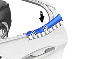
.png) | Install in this Direction |
3. INSTALL REAR DOOR BELT MOULDING ASSEMBLY
(a) Engage the guide and 5 claws to install a new rear door belt moulding assembly as shown in the illustration.
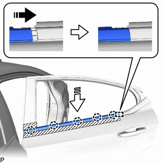
| | Install in this Direction (1) |
.png) | Install in this Direction (2) |
4. INSTALL REAR DOOR GLASS SUB-ASSEMBLY
Click here
5. INSTALL REAR DOOR QUARTER WINDOW GLASS SUB-ASSEMBLY
Click here
6. INSTALL REAR DOOR WINDOW DIVISION BAR SUB-ASSEMBLY
Click here
7. CONNECT REAR DOOR WEATHERSTRIP
Click here
8. INSTALL REAR DOOR GLASS RUN
Click here
9. INSTALL REAR DOOR PANEL PROTECTOR
Click here
10. INSTALL REAR DOOR NO. 2 VENT SEAL
Click here
11. INSTALL REAR DOOR NO. 2 SERVICE HOLE COVER
Click here
12. INSTALL REAR DOOR SERVICE HOLE COVER
Click here
13. INSTALL REAR SIDE CURTAIN ASSEMBLY (w/ Rear Door Sunshade)
Click here
14. INSTALL REAR DOOR TRIM BOARD SUB-ASSEMBLY
Click here
15. INSTALL COURTESY LIGHT ASSEMBLY
Click here
16. INSTALL REAR DOOR TRIM UPPER PAD
Click here
17. INSTALL REAR POWER WINDOW REGULATOR SWITCH ASSEMBLY WITH REAR DOOR UPPER ARMREST BASE PANEL
Click here
18. CONNECT CABLE TO NEGATIVE AUXILIARY BATTERY TERMINAL
for 2GR-FKS:
Click here
for A25A-FXS:
Click here
for A25A-FKS:
Click here
19. INITIALIZE POWER WINDOW CONTROL SYSTEM
for HV Model:
Click here
for Gasoline Model:
Click here
20. INSPECT POWER WINDOW OPERATION
for HV Model:
Click here
for Gasoline Model:
Click here
READ NEXT:
 Components
COMPONENTS ILLUSTRATION *1 REAR DOOR FRONT WINDOW FRAME MOULDING *2 REAR DOOR WEATHERSTRIP *3 REAR DOOR WINDOW FRAME MOULDING SUB-ASSEMBLY *4 RIVET ● Non-reusable part -
Removal
REMOVAL CAUTION / NOTICE / HINT The necessary procedures (adjustment, calibration, initialization, or registration) that must be performed after parts are removed and installed, or replaced during rea
SEE MORE:
Disassembly
DISASSEMBLY CAUTION / NOTICE / HINT HINT:
Use the same procedure for the RH side and LH side.
The following procedure is for the LH side.
PROCEDURE 1. REMOVE REAR LIGHT GASKET (a) Remove the rear light gasket. NOTICE:
Be sure to remove all traces of the old rear light gasket from the
VSC OFF Switch Circuit
DESCRIPTION The skid control ECU (brake actuator assembly) is connected to the combination meter assembly via CAN communication. Pressing the VSC OFF switch turns off TRAC operation, and pressing and holding this switch turns off TRAC and VSC operation. If TRAC and VSC operations are turned off, "Tr
