Lexus ES: VSC OFF Switch Circuit
DESCRIPTION
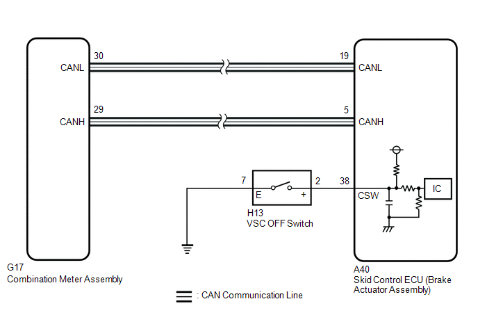
The skid control ECU (brake actuator assembly) is connected to the combination meter assembly via CAN communication.
Pressing the VSC OFF switch turns off TRAC operation, and pressing and holding this switch turns off TRAC and VSC operation. If TRAC and VSC operations are turned off, "Traction Control Turned Off" will be displayed on the multi-information display and the VSC OFF indicator light will come on.
WIRING DIAGRAM
CAUTION / NOTICE / HINT
NOTICE:
After replacing the skid control ECU (brake actuator assembly), perform acceleration sensor zero point calibration and store system information memorization.
Click here .gif)
PROCEDURE
| 1. | READ VALUE USING TECHSTREAM (TRAC/VSC OFF MODE) |
(a) Connect the Techstream to the DLC3.
(b) Turn the engine switch on (IG).
(c) Enter the following menus: Chassis / Brake/EPB / Data List.
Chassis > Brake/EPB > Data List| Tester Display | Measurement Item | Range | Normal Condition | Diagnostic Note |
|---|---|---|---|---|
| TRC(TRAC)/VSC OFF Mode | TRAC/VSC off mode | Normal mode (TRC(TRAC) ON/VSC ON) / TRC(TRAC) OFF mode (TRC(TRAC) OFF/VSC ON) / Not defined / VSC OFF mode (TRC(TRAC) OFF/VSC OFF) | Normal mode (TRC(TRAC) ON/VSC ON): Normal mode TRC(TRAC) OFF mode (TRC(TRAC) OFF/VSC ON): TRAC off mode Not defined: Not defined VSC OFF mode (TRC(TRAC) OFF/VSC OFF): VSC off mode | - |
| Tester Display |
|---|
| TRC(TRAC)/VSC OFF Mode |
(d) Check the indicator light and mode condition on the Techstream changes according to VSC OFF switch operation.
Standard:
| Switch Operation | Mode Condition Display | Multi-information Display ("Traction Control Turned Off") | VSC OFF Indicator Light |
|---|---|---|---|
| Not pressed | Normal mode (TRC(TRAC) ON/VSC ON) | Not displayed | Does not come on |
| Pressing the VSC OFF switch | TRC(TRAC) OFF mode (TRC(TRAC) OFF/VSC ON) | Displayed | Does not come on |
| Pressing and holding the VSC OFF switch | VSC OFF mode (TRC(TRAC) OFF/VSC OFF) | Displayed | Comes on |
| Result | Proceed to |
|---|---|
| Indicator light and mode condition display do not change | A |
| Mode condition display is normal, but indicator light does not change | B |
| Indicator light and mode condition display are normal | C |
| B | .gif) | INSPECT METER / GAUGE SYSTEM |
| C | | USE SIMULATION METHOD TO CHECK |
|
.gif)
| 2. | INSPECT VSC OFF SWITCH |
| (a) Make sure that there is no looseness at the locking part and the connecting part of the connector. OK: The connector is securely connected. |
|
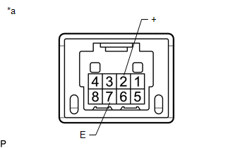
(b) Disconnect the H13 VSC OFF switch connector.
(c) Check both the connector case and the terminal for deformation and corrosion.
OK:
No deformation or corrosion.
(d) Measure the resistance according to the value(s) in the table below.
Standard Resistance:
| Tester Connection | Condition | Specified Condition |
|---|---|---|
| 2 (+) - 7 (E) | Switch pushed | Below 1 Ω |
| 2 (+) - 7 (E) | Switch not pushed | 10 kΩ or higher |
| NG | | REPLACE VSC OFF SWITCH |
|
| 3. | CHECK HARNESS AND CONNECTOR (BRAKE ACTUATOR ASSEMBLY - VSC OFF SWITCH) |
(a) Make sure that there is no looseness at the locking part and the connecting part of the connector.
OK:
The connector is securely connected.
(b) Disconnect the A40 skid control ECU (brake actuator assembly) connector.
(c) Disconnect the H13 VSC OFF switch connector.
(d) Check both the connector case and the terminals for deformation and corrosion.
OK:
No deformation or corrosion.
(e) Measure the resistance according to the value(s) in the table below.
Standard Resistance:
| Tester Connection | Condition | Specified Condition |
|---|---|---|
| H13-2 (+) - A40-38 (CSW) | Always | Below 1 Ω |
| H13-2 (+) or A40-38 (CSW) - Body ground | Always | 10 kΩ or higher |
| H13-7 (E) - Body ground | Always | Below 1 Ω |
| OK | | REPLACE BRAKE ACTUATOR ASSEMBLY |
| NG | | REPAIR OR REPLACE HARNESS OR CONNECTOR |
READ NEXT:
 Yaw Rate Sensor Wrong Installation (X0456)
DESCRIPTION The airbag ECU assembly has a built-in yaw rate and acceleration sensor and detects the vehicle condition. Code Tester Display Measurement Item Trouble Area X0456 Yaw Rate S
Zero Point Calibration of Steering Angle Sensor Initialization Malfunction (X208A)
DESCRIPTION Code Tester Display Measurement Item Trouble Area X208A Zero Point Calibration of Steering Angle Sensor Initialization Malfunction History of failure in acquiring steering
SEE MORE:
Dtc Check / Clear
DTC CHECK / CLEAR CHECK DTC (a) Connect the Techstream to the DLC3. (b) Turn the engine switch on (IG). (c) Turn the Techstream on. (d) Enter the following menus: Body Electrical / Mirror L or Mirror R / Trouble Codes. Body Electrical > Mirror L > Trouble Codes Body Electrical > Mirror R &g
Accumulator Pressure Sensor Stuck (C14D5)
DESCRIPTION The accumulator pressure sensor is built into the brake booster with master cylinder assembly and detects the accumulator pressure. If the skid control ECU (brake booster with master cylinder assembly) detects that the accumulator pressure sensor value is below the threshold, operation o
