Lexus ES: Installation
INSTALLATION
PROCEDURE
1. INSTALL HAZARD WARNING SIGNAL SWITCH ASSEMBLY
(a) Engage the 2 claws to install the hazard warning signal switch assembly.
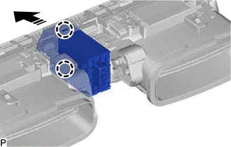
.png) | Install in this Direction |
2. INSTALL NO. 2 INSTRUMENT PANEL REGISTER ASSEMBLY
Click here .gif)
3. INSTALL UPPER INSTRUMENT PANEL FINISH PANEL SUB-ASSEMBLY
Click here
4. INSTALL INSTRUMENT CLUSTER FINISH PANEL SUB-ASSEMBLY (w/o Headup Display)
Click here
5. INSTALL INSTRUMENT CLUSTER FINISH PANEL SUB-ASSEMBLY (w/ Headup Display)
Click here
6. INSTALL NO. 1 INSTRUMENT CLUSTER MOULDING
Click here
7. INSTALL LOWER INSTRUMENT PANEL FINISH PANEL SUB-ASSEMBLY
Click here
8. INSTALL NO. 1 INSTRUMENT PANEL UNDER COVER SUB-ASSEMBLY
Click here
9. INSTALL INSTRUMENT SIDE PANEL LH
Click here
10. INSTALL FRONT DOOR OPENING TRIM COVER LH
Click here
11. INSTALL COWL SIDE TRIM BOARD LH
Click here
12. INSTALL FRONT DOOR SCUFF PLATE LH
Click here
13. INSTALL AIR CONDITIONING CONTROL ASSEMBLY
Click here
READ NEXT:
 Components
COMPONENTS ILLUSTRATION *1 COWL TOP PANEL INSULATOR *2 FRONT FENDER SPLASH SHIELD SUB-ASSEMBLY *3 HEADLIGHT ASSEMBLY - - N*m (kgf*cm, ft.*lbf): Specified torque - - I
Removal
REMOVAL CAUTION / NOTICE / HINT The necessary procedures (adjustment, calibration, initialization or registration) that must be performed after parts are removed and installed, or replaced during head
SEE MORE:
Left Rear Wheel Speed Sensor Circuit Short to Battery (C050C12)
DESCRIPTION Each speed sensor detects wheel speed and sends signals to the skid control ECU (brake actuator assembly). These signals are used by the ABS control. The speed sensor detects the magnetic fields of the speed sensor rotor as it rotates and outputs a pulse signal. The frequency of the puls
Drive Motor Inverter Temperature Sensor "A" Circuit Voltage Out of Range (P0AED1C)
DTC SUMMARY MALFUNCTION DESCRIPTION These DTCs indicate that the motor inverter temperature sensor value is abnormal. The cause of this malfunction may be one of the following: Internal inverter malfunction
Inverter with converter assembly internal circuit malfunction
Hybrid cooling system ma
