Lexus ES: Components
COMPONENTS
ILLUSTRATION
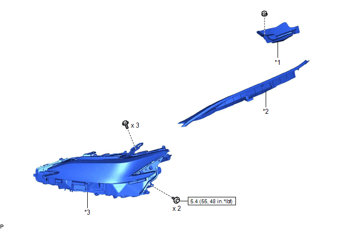
| *1 | COWL TOP PANEL INSULATOR | *2 | FRONT FENDER SPLASH SHIELD SUB-ASSEMBLY |
| *3 | HEADLIGHT ASSEMBLY | - | - |
.png) | N*m (kgf*cm, ft.*lbf): Specified torque | - | - |
ILLUSTRATION
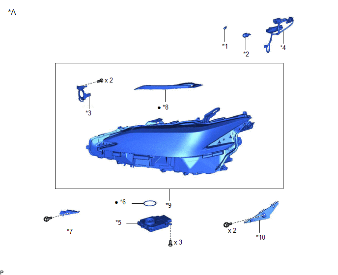
| *A | for TMC Made | - | - |
| *1 | FRONT SIDE MARKER LIGHT BULB | *2 | FRONT TURN SIGNAL LIGHT BULB |
| *3 | HEADLIGHT BRACKET | *4 | HEADLIGHT CORD |
| *5 | HEADLIGHT ECU SUB-ASSEMBLY | *6 | HEADLIGHT GASKET |
| *7 | HEADLIGHT RIM | *8 | HEADLIGHT SEAL |
| *9 | HEADLIGHT UNIT ASSEMBLY | *10 | NO. 2 HEADLIGHT FITTING RIM |
| ● | Non-reusable part | - | - |
ILLUSTRATION
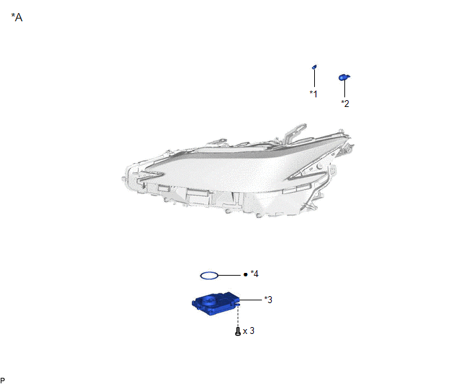
| *A | for TMMK Made | - | - |
| *1 | FRONT SIDE MARKER LIGHT BULB | *2 | FRONT TURN SIGNAL LIGHT BULB |
| *3 | HEADLIGHT ECU SUB-ASSEMBLY | *4 | HEADLIGHT GASKET |
| ● | Non-reusable part | - | - |
ILLUSTRATION
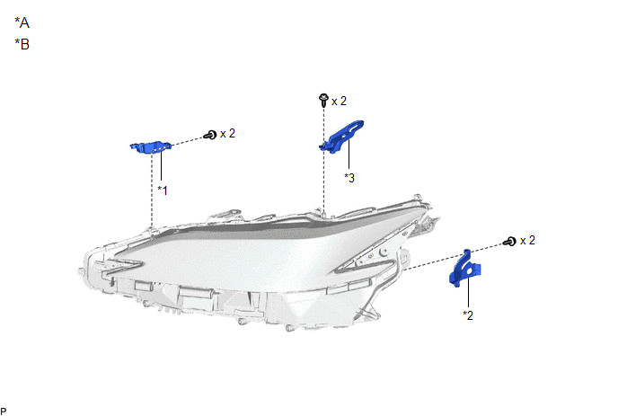
| *A | Bracket for Repair | *B | for TMC Made |
| *1 | LOWER HEADLIGHT PROTECTOR RETAINER | *2 | LOWER NO. 2 HEADLIGHT PROTECTOR RETAINER |
| *3 | UPPER HEADLIGHT PROTECTOR RETAINER | - | - |
READ NEXT:
 Removal
REMOVAL CAUTION / NOTICE / HINT The necessary procedures (adjustment, calibration, initialization or registration) that must be performed after parts are removed and installed, or replaced during head
Disassembly
DISASSEMBLY CAUTION / NOTICE / HINT HINT:
Use the same procedure for the RH side and LH side.
The following procedure is for the LH side.
PROCEDURE 1. REMOVE HEADLIGHT ECU SUB-ASSEMBLY Click h
Adjustment
ADJUSTMENT CAUTION / NOTICE / HINT HINT:
Use the same procedure for the RH side and LH side.
The following procedure is for the LH side.
PROCEDURE 1. PREPARE VEHICLE FOR HEADLIGHT AIM ADJUSTME
SEE MORE:
How To Proceed With Troubleshooting
CAUTION / NOTICE / HINT HINT:
Use these procedures to troubleshoot the heated steering wheel system.
*: Use the Techstream.
PROCEDURE 1. VEHICLE BROUGHT TO WORKSHOP
NEXT 2. INSPECT BATTERY VOLTAGE (a) Measure the battery voltage with the engine switch off.
Fuel Pressure Sensor
ComponentsCOMPONENTS ILLUSTRATION *1 NO. 2 FUEL PRESSURE SENSOR *2 NO. 2 FUEL PRESSURE SENSOR HOLDER *3 O-RING - - Tightening torque for "Major areas involving basic vehicle performance such as moving/turning/stopping": N*m (kgf*cm, ft.*lbf) ● Non-reusable part
© 2016-2026 Copyright www.lexguide.net
