Lexus ES: Left Rear Wheel Speed Sensor Circuit Short to Battery (C050C12)
DESCRIPTION
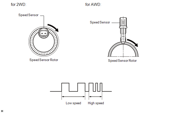
Each speed sensor detects wheel speed and sends signals to the skid control ECU (brake actuator assembly). These signals are used by the ABS control.
The speed sensor detects the magnetic fields of the speed sensor rotor as it rotates and outputs a pulse signal.
The frequency of the pulse varies in accordance with the rotational speed of the speed sensor rotor and the system uses this to determine the wheel speed.
HINT:
The following example shows a pulse signal that is output when the wire harness connectors are connected to the speed sensors and skid control ECU (brake actuator assembly).
| DTC No. | Detection Item | DTC Detection Condition | Trouble Area |
|---|---|---|---|
| C050C12 | Left Rear Wheel Speed Sensor Circuit Short to Battery | A short to +B in the speed sensor signal circuit is detected for 0.12 seconds or more. |
|
*1: for 2WD
*2: for AWD
WIRING DIAGRAM
for 2WD (w/o AVS)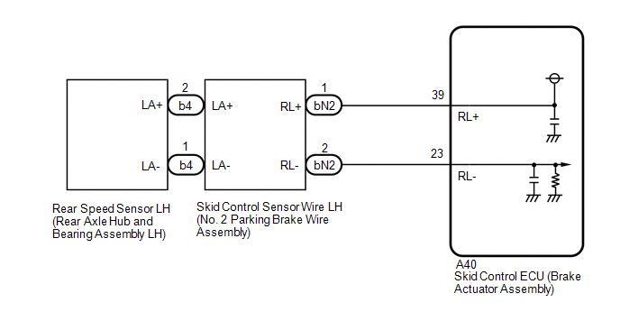 for 2WD (w/ AVS)
 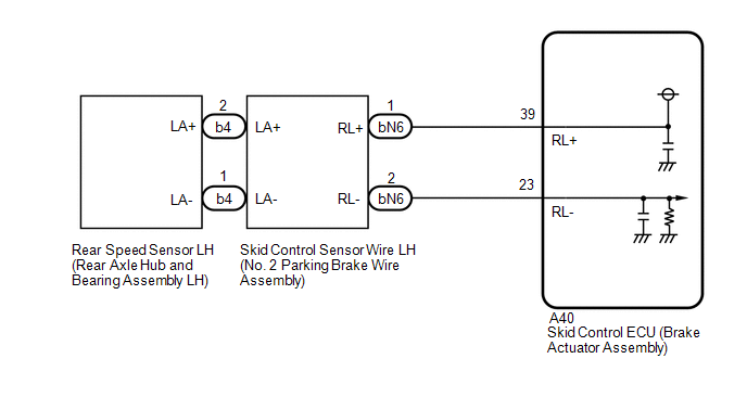 for AWD
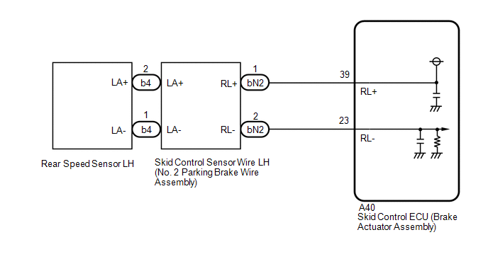
CAUTION / NOTICE / HINT
NOTICE:
-
After replacing the skid control ECU (brake actuator assembly), perform acceleration sensor zero point calibration and store system information memorization.
Click here
.gif)
-
After replacing or removing and installing a speed sensor, perform Dealer Mode (Signal Check) inspection to confirm that the speed sensors are operating correctly.
Click here
PROCEDURE
| 1. | CHECK VEHICLE |
(a) Check the vehicle specification.
| Result | Proceed to |
|---|---|
| for 2WD (w/o AVS) | A |
| for 2WD (w/ AVS) | B |
| for AWD | C |
| B |  | GO TO STEP 6 |
| C | | GO TO STEP 10 |
|

| 2. | CHECK HARNESS AND CONNECTOR (SENSOR GROUND CIRCUIT) |
| (a) Make sure that there is no looseness at the locking part and the connecting part of the connectors. OK: The connector is securely connected. |
|
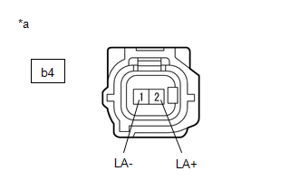
(b) Disconnect the b4 rear speed sensor LH (rear axle hub and bearing assembly LH) connector.
(c) Check both the connector case and the terminals for deformation and corrosion.
OK:
No deformation or corrosion.
(d) Turn the engine switch on (IG).
(e) Measure the voltage according to the value(s) in the table below.
Standard Voltage:
| Tester Connection | Condition | Specified Condition |
|---|---|---|
| b4-2 (LA+) - b4-1 (LA-) | Engine switch on (IG) | 11 to 14 V |
| OK | | REPLACE REAR AXLE HUB AND BEARING ASSEMBLY LH |
|
| 3. | CHECK HARNESS AND CONNECTOR (SENSOR GROUND CIRCUIT) |
| (a) Make sure that there is no looseness at the locking part and the connecting part of the connectors. OK: The connector is securely connected. |
|
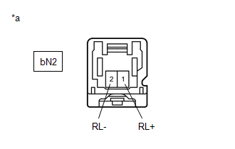
(b) Disconnect the bN2 skid control sensor wire LH (No. 2 parking brake wire assembly) connector.
(c) Check both the connector case and the terminals for deformation and corrosion.
OK:
No deformation or corrosion.
(d) Turn the engine switch on (IG).
(e) Measure the voltage according to the value(s) in the table below.
Standard Voltage:
| Tester Connection | Condition | Specified Condition |
|---|---|---|
| bN2-1 (RL+) - bN2-2 (RL-) | Engine switch on (IG) | 11 to 14 V |
| OK | | REPLACE NO. 2 PARKING BRAKE WIRE ASSEMBLY |
|
| 4. | CHECK HARNESS AND CONNECTOR (NO. 2 PARKING BRAKE WIRE ASSEMBLY - BRAKE ACTUATOR ASSEMBLY) |
| (a) Make sure that there is no looseness at the locking part and the connecting part of the connectors. OK: The connector is securely connected. |
|

(b) Disconnect the A40 skid control ECU (brake actuator assembly) connector.
(c) Disconnect the bN2 skid control sensor wire LH (No. 2 parking brake wire assembly) connector.
(d) Check both the connector case and the terminals for deformation and corrosion.
OK:
No deformation or corrosion.
(e) Measure the voltage according to the value(s) in the table below.
Standard Voltage:
| Tester Connection | Condition | Specified Condition |
|---|---|---|
| bN2-2 (RL-) - Body ground | Always | Below 1.5 V |
| NG | | REPAIR OR REPLACE HARNESS OR CONNECTOR |
|
| 5. | CHECK HARNESS AND CONNECTOR (NO. 2 PARKING BRAKE WIRE ASSEMBLY - BRAKE ACTUATOR ASSEMBLY) |
(a) Make sure that there is no looseness at the locking part and the connecting part of the connectors.
OK:
The connector is securely connected.
(b) Disconnect the A40 skid control ECU (brake actuator assembly) connector.
(c) Disconnect the bN2 skid control sensor wire LH (No. 2 parking brake wire assembly) connector.
(d) Check both the connector case and the terminals for deformation and corrosion.
OK:
No deformation or corrosion.
(e) Measure the resistance according to the value(s) in the table below.
Standard Resistance:
| Tester Connection | Condition | Specified Condition |
|---|---|---|
| bN2-1 (RL+) or A40-39 (RL+) - bN2-2 (RL-) or A40-23 (RL-) | Always | 10 kΩ or higher |
| OK | | REPLACE BRAKE ACTUATOR ASSEMBLY |
| NG | | REPAIR OR REPLACE HARNESS OR CONNECTOR |
| 6. | CHECK HARNESS AND CONNECTOR (SENSOR GROUND CIRCUIT) |
| (a) Make sure that there is no looseness at the locking part and the connecting part of the connectors. OK: The connector is securely connected. |
|
(b) Disconnect the b4 rear speed sensor LH (rear axle hub and bearing assembly LH) connector.
(c) Check both the connector case and the terminals for deformation and corrosion.
OK:
No deformation or corrosion.
(d) Turn the engine switch on (IG).
(e) Measure the voltage according to the value(s) in the table below.
Standard Voltage:
| Tester Connection | Condition | Specified Condition |
|---|---|---|
| b4-2 (LA+) - b4-1 (LA-) | Engine switch on (IG) | 11 to 14 V |
| OK | | REPLACE REAR AXLE HUB AND BEARING ASSEMBLY LH |
|
| 7. | CHECK HARNESS AND CONNECTOR (SENSOR GROUND CIRCUIT) |
| (a) Make sure that there is no looseness at the locking part and the connecting part of the connectors. OK: The connector is securely connected. |
|
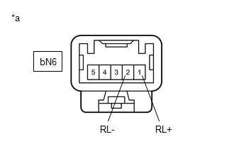
(b) Disconnect the bN6 skid control sensor wire LH (No. 2 parking brake wire assembly) connector.
(c) Check both the connector case and the terminals for deformation and corrosion.
OK:
No deformation or corrosion.
(d) Turn the engine switch on (IG).
(e) Measure the voltage according to the value(s) in the table below.
Standard Voltage:
| Tester Connection | Condition | Specified Condition |
|---|---|---|
| bN6-1 (RL+) - bN6-2 (RL-) | Engine switch on (IG) | 11 to 14 V |
| OK | | REPLACE NO. 2 PARKING BRAKE WIRE ASSEMBLY |
|
| 8. | CHECK HARNESS AND CONNECTOR (NO. 2 PARKING BRAKE WIRE ASSEMBLY - BRAKE ACTUATOR ASSEMBLY) |
| (a) Make sure that there is no looseness at the locking part and the connecting part of the connectors. OK: The connector is securely connected. |
|
(b) Disconnect the A40 skid control ECU (brake actuator assembly) connector.
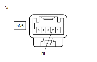
(c) Disconnect the bN6 skid control sensor wire LH (No. 2 parking brake wire assembly) connector.
(d) Check both the connector case and the terminals for deformation and corrosion.
OK:
No deformation or corrosion.
(e) Measure the voltage according to the value(s) in the table below.
Standard Voltage:
| Tester Connection | Condition | Specified Condition |
|---|---|---|
| bN6-2 (RL-) - Body ground | Always | Below 1.5 V |
| NG | | REPAIR OR REPLACE HARNESS OR CONNECTOR |
|
| 9. | CHECK HARNESS AND CONNECTOR (NO. 2 PARKING BRAKE WIRE ASSEMBLY - BRAKE ACTUATOR ASSEMBLY) |
(a) Make sure that there is no looseness at the locking part and the connecting part of the connectors.
OK:
The connector is securely connected.
(b) Disconnect the A40 skid control ECU (brake actuator assembly) connector.
(c) Disconnect the bN6 skid control sensor wire LH (No. 2 parking brake wire assembly) connector.
(d) Check both the connector case and the terminals for deformation and corrosion.
OK:
No deformation or corrosion.
(e) Measure the resistance according to the value(s) in the table below.
Standard Resistance:
| Tester Connection | Condition | Specified Condition |
|---|---|---|
| bN6-1 (RL+) or A40-39 (RL+) - bN6-2 (RL-) or A40-23 (RL-) | Always | 10 kΩ or higher |
| OK | | REPLACE BRAKE ACTUATOR ASSEMBLY |
| NG | | REPAIR OR REPLACE HARNESS OR CONNECTOR |
| 10. | CHECK HARNESS AND CONNECTOR (SENSOR GROUND CIRCUIT) |
| (a) Make sure that there is no looseness at the locking part and the connecting part of the connectors. OK: The connector is securely connected. |
|
(b) Disconnect the b4 rear speed sensor LH connector.
(c) Check both the connector case and the terminals for deformation and corrosion.
OK:
No deformation or corrosion.
(d) Turn the engine switch on (IG).
(e) Measure the voltage according to the value(s) in the table below.
Standard Voltage:
| Tester Connection | Condition | Specified Condition |
|---|---|---|
| b4-2 (LA+) - b4-1 (LA-) | Engine switch on (IG) | 11 to 14 V |
| OK | | REPLACE REAR SPEED SENSOR LH |
| NG | | GO TO STEP 3 |
READ NEXT:
 Left Rear Wheel Speed Sensor Circuit Short to Ground or Open (C050C14)
DESCRIPTION Refer to DTC C050C12 Click here DTC No. Detection Item DTC Detection Condition Trouble Area C050C14 Left Rear Wheel Speed Sensor Circuit Short to Ground or Open A short
Left Rear Wheel Speed Sensor Circuit Short to Ground or Open (C050C14)
DESCRIPTION Refer to DTC C050C12 Click here DTC No. Detection Item DTC Detection Condition Trouble Area C050C14 Left Rear Wheel Speed Sensor Circuit Short to Ground or Open A short
Left Rear Wheel Speed Sensor Signal Stuck Low (C050C23)
DESCRIPTION Refer to DTC C050C12 Click here DTC No. Detection Item DTC Detection Condition Trouble Area C050C23 Left Rear Wheel Speed Sensor Signal Stuck Low
When the vehicle is
SEE MORE:
Blind Spot Monitor Slave Module (C1AB7)
DESCRIPTION This DTC is stored when the blind spot monitor sensor LH detects an internal malfunction. DTC No. Detection Item DTC Detection Condition Trouble Area C1AB7 Blind Spot Monitor Slave Module The blind spot monitor sensor LH (slave) detects an internal malfunction Blind sp
Air Bag Circuit (C147D)
DESCRIPTION The skid control ECU (brake booster with master cylinder assembly) receives the secondary collision brake control request signal from the airbag ECU assembly. DTC No. Detection Item INF Code DTC Detection Condition Trouble Area MIL Note C147D Air Bag Circuit 451
