Lexus ES: Installation
INSTALLATION
PROCEDURE
1. INSTALL NO. 3 ANTENNA CORD SUB-ASSEMBLY (w/ Manual (SOS) Switch)
(a) Engage the 5 clamps to install the No. 3 antenna cord sub-assembly.
(b) Connect the connector.
2. INSTALL NO. 2 ANTENNA CORD SUB-ASSEMBLY
HINT:
Butyl tape and adhesive tape are not available as supply parts. If these pieces of tape still have enough adhesion to secure the No. 2 antenna cord sub-assembly to the roof headlining assembly, reuse them. If the adhesive tape and/or the butyl tape is no longer sticky, apply new tape following the procedure below.
(a) Apply new butyl tape.
for Moon Roof:
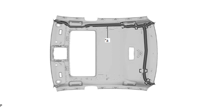
| *a | Marking | - | - |
 | Butyl Tape | - | - |
for Panoramic Moon Roof:
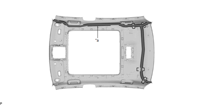
| *a | Marking | - | - |
| | Butyl Tape | - | - |
(1) Remove the old butyl tape from the roof headlining assembly.
(2) Prepare an appropriate amount of new butyl tape.
HINT:
Be careful not to touch the adhesive surface.
(3) Apply the butyl tape to the roof headlining assembly while aligning the tape with the markings on the roof headlining assembly.
(4) Peel off the release paper from the butyl tape.
(b) Align the marking tape (A) and marking tape (B) of the No. 2 antenna cord sub-assembly with the edge of the rear side of the headlining assembly, near each protrusion, and wrap adhesive tape around the protrusion and No. 2 antenna cord sub-assembly to secure them as shown in the illustration.
for Moon Roof:
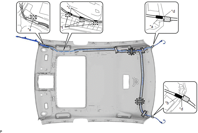
| *a | Marking Tape (A) | *b | Marking Tape (B) |
| *c | Marking Tape (C) | *d | Edge |
| *e | Clamp | *f | Guide |
 | Adhesive Tape |  | Adjustment Area |
for Panoramic Moon Roof:
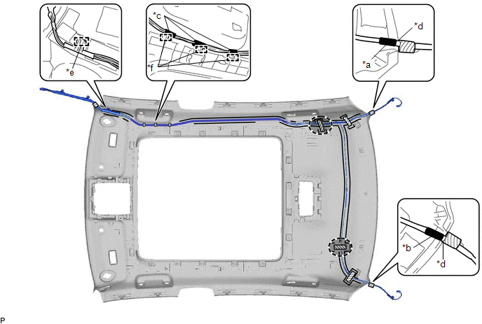
| *a | Marking Tape (A) | *b | Marking Tape (B) |
| *c | Marking Tape (C) | *d | Edge |
| *e | Clamp | *f | Guide |
| | Adhesive Tape | | Adjustment Area |
(c) Engage the clamp.
(d) Align each marking tape (C) of the No. 2 antenna cord sub-assembly with each guide and engage the 3 guides.
(e) Install the No. 2 antenna cord sub-assembly to the roof headlining assembly.
NOTICE:
- Make sure that there are no gaps between the roof headlining assembly and No. 2 antenna cord sub-assembly, and that the No. 2 antenna cord sub-assembly is not twisted.
- Make sure the No. 2 antenna cord sub-assembly is securely installed. If any part of the No. 2 antenna cord sub-assembly is loose, it will cause an abnormal noise.
HINT:
Secure the extra length of the No. 2 antenna cord sub-assembly in the adjustment area.
(f) Apply the adhesive tape as shown in the illustration to secure the No. 2 antenna cord sub-assembly.
3. INSTALL ROOF HEADLINING ASSEMBLY
Click here .gif)
4. INSTALL ANTENNA CORD SUB-ASSEMBLY
(a) w/o Manual (SOS) Switch:
(1) Engage the 7 clamps to install the antenna cord sub-assembly.
(b) w/ Manual (SOS) Switch:
(1) Engage the 8 clamps to install the antenna cord sub-assembly.
(c) Engage the 2 claws.
(d) Connect the connector.
5. INSTALL NO. 3 HEATER TO REGISTER DUCT
Click here
6. INSTALL NO. 2 SIDE DEFROSTER NOZZLE DUCT
Click here
7. INSTALL INSTRUMENT PANEL SAFETY PAD SUB-ASSEMBLY
Click here
READ NEXT:
 Removal
REMOVAL CAUTION / NOTICE / HINT The necessary procedures (adjustment, calibration, initialization, or registration) that must be performed after parts are removed and installed, or replaced during ant
Components
COMPONENTS ILLUSTRATION *1 CENTER INSTRUMENT CLUSTER FINISH PANEL SUB-ASSEMBLY *2 INSTRUMENT PANEL FINISH PANEL END LH *3 INSTRUMENT PANEL FINISH PANEL END RH *4 REAR UPPER CONSOLE
SEE MORE:
Brake Pressure Control Solenoid "B" Control Circuit Short to Battery (C13C912,...,C13C949)
DESCRIPTION The ABS solenoid relay and master cylinder cut solenoid valves are built into the brake actuator assembly. Depending on the operating conditions, the master cylinder cut solenoid valves regulates the brake fluid pressure generated by the pump motor. When this DTC is stored, the fail-safe
Intake System
On-vehicle InspectionON-VEHICLE INSPECTION CAUTION / NOTICE / HINT The necessary procedures (adjustment, calibration, initialization or registration) that must be performed after parts are removed and installed, or replaced when repairing air leaks in the intake system are shown below. Necessary Pr
