Lexus ES: Inspection
INSPECTION
PROCEDURE
1. INSPECT TRANSMISSION OIL CLEANER MAGNET
| (a) Use the removed transmission oil cleaner magnets to collect any steel chips. Examine the chips and particles in the transaxle housing and on the transmission oil cleaner magnets to determine what type of wear might be found in the automatic transaxle assembly. Result: Steel (magnetic) Bearing, gear and plate wear Brass (non-magnetic) Bushing wear |
|
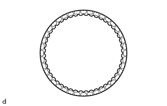
2. INSPECT FRONT CLUTCH CLUTCH DISC
| (a) Check if the contact surfaces of the front clutch clutch disc, forward multiple disc clutch clutch plate and forward clutch flange are worn or burnt. If necessary, replace them. NOTICE:
|
|
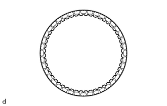
3. INSPECT NO. 2 CLUTCH DISC
| (a) Check if the contact surfaces of the No. 2 clutch disc, No. 2 clutch plate and direct clutch flange are worn or burnt. If necessary, replace them. NOTICE:
|
|
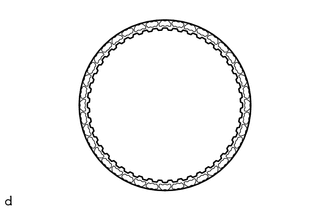
4. INSPECT NO. 1 BRAKE DISC
| (a) Check if the contact surfaces of the No. 1 brake disc, No. 1 brake plate and No. 1 brake flange are worn or burnt. If necessary, replace them. NOTICE:
|
|
5. INSPECT 2ND BRAKE BRAKE DISC
| (a) Check if the contact surfaces of the 2nd brake brake disc, 2nd brake brake plate and 2nd brake brake flange are worn or burnt. If necessary, replace them. NOTICE:
|
|
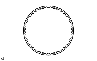
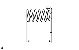
6. INSPECT CLUTCH RETURN SPRING SUB-ASSEMBLY
| (a) Using a vernier caliper, measure the free length of the clutch return spring sub-assembly together with the spring seat. Standard Free Length: 14.61 mm (0.575 in.) If the free length is shorter than the standard free length, replace the clutch return spring sub-assembly. |
|
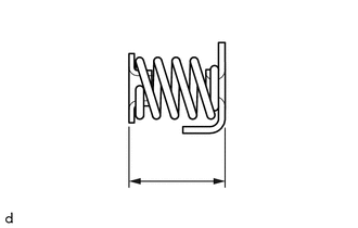
7. INSPECT 1ST AND REVERSE BRAKE RETURN SPRING SUB-ASSEMBLY
| (a) Using a vernier caliper, measure the free length of the 1st and reverse brake return spring sub-assembly together with the spring seat. Standard Free Length: 18.29 mm (0.720 in.) If the free length is shorter than the standard free length, replace the 1st and reverse brake return spring sub-assembly. |
|
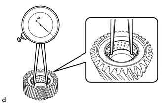
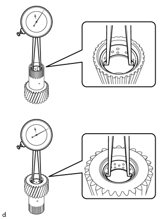
8. INSPECT PLANETARY SUN GEAR SUB-ASSEMBLY
| (a) Using a caliper gauge, measure the inside diameter of the bushing of the planetary sun gear sub-assembly. Standard Inside Diameter: 33.286 to 33.312 mm (1.310 to 1.311 in.) Maximum Inside Diameter: 33.312 mm (1.311 in.) If the inside diameter is more than the maximum, replace the planetary sun gear sub-assembly. |
|
9. INSPECT REAR PLANETARY SUN GEAR SUB-ASSEMBLY
| (a) Using a caliper gauge, measure the inside diameter of the bushing of the rear planetary sun gear sub-assembly. Standard Inside Diameter: 24.287 to 24.313 mm (0.956 to 0.957 in.) Maximum Inside Diameter: 24.313 mm (0.957 in.) If the inside diameter is more than the maximum, replace the rear planetary sun gear sub-assembly. |
|
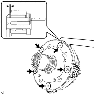
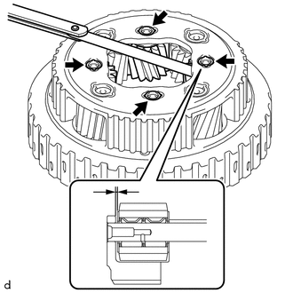
10. INSPECT FRONT PLANETARY GEAR ASSEMBLY
| (a) for Outer Pinion: (1) Using a feeler gauge, measure the clearance between the planetary carrier and pinion gears at 5 points. Standard Clearance: 0.2 to 0.6 mm (0.00787 to 0.0236 in.) If the clearance is more than the standard clearance, replace the front planetary gear assembly. |
|
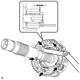
| (b) for Inner Pinion: (1) Using a feeler gauge, measure the clearance between the planetary carrier and pinion gears at 5 points. Standard Clearance: 0.2 to 0.6 mm (0.00787 to 0.0236 in.) If the clearance is more than the standard clearance, replace the front planetary gear assembly. |
|
11. INSPECT REAR PLANETARY GEAR ASSEMBLY
| (a) for Long Pinion: (1) Using a feeler gauge, measure the clearance between the planetary carrier and pinion gears at 4 points. Standard Clearance: 0.15 to 1.05 mm (0.00591 to 0.0413 in.) If the clearance is more than the standard clearance, replace the rear planetary gear assembly. |
|
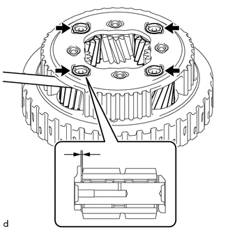
| (b) for Short Pinion: (1) Using a feeler gauge, measure the clearance between the planetary carrier and pinion gears at 4 points. Standard Clearance: 0.15 to 0.85 mm (0.00591 to 0.0335 in.) If the clearance is more than the standard clearance, replace the rear planetary gear assembly. |
|
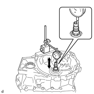
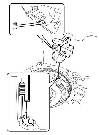
12. INSPECT INPUT SHAFT END PLAY
| (a) Using a dial indicator, measure the input shaft end play. Standard Input Shaft End Play: 0.332 to 1.103 mm (0.0131 to 0.0434 in.) |
|
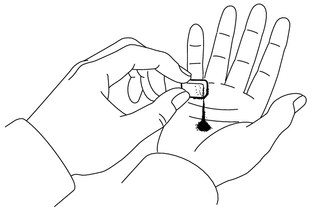
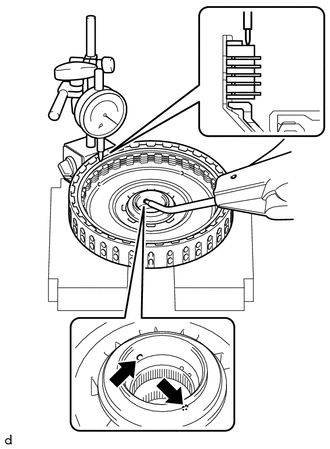
13. INSPECT CLEARANCE OF C-3 CLUTCH
(a) Set the C-3 and C-4 clutch assembly on the front oil pump assembly.
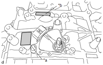
(b) Using a dial indicator, measure the clearance of the C-3 clutch while applying compressed air (approximately 200 kPa (2.0 kgf/cm2, 29 psi)).
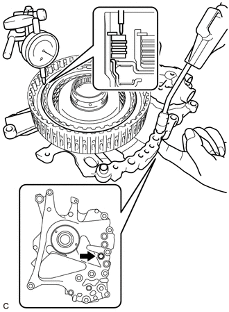
.png) | Cover Oil Hole |
Pack Clearance (Reference):
0.19 to 0.61 mm (0.00748 to 0.0240 in.)
HINT:
- Cover the location shown in the illustration with your finger when applying compressed air.
- To find the clearance, measure in at least 3 locations and average the results.
If the clearance is not as specified, replace the C-3 and C-4 clutch assembly.
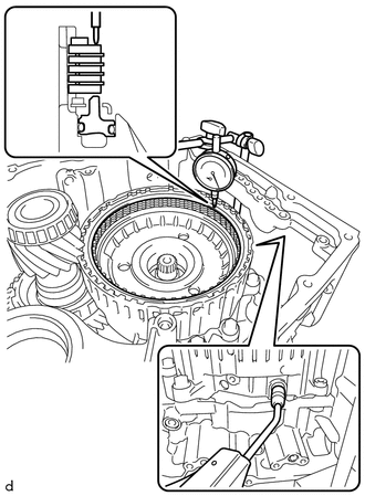
14. INSPECT CLEARANCE OF C-4 CLUTCH
(a) Set the C-3 and C-4 clutch assembly on the front oil pump assembly.
(b) Using a dial indicator, measure the clearance of the C-4 clutch while applying compressed air (approximately 400 kPa (4.1 kgf/cm2, 58 psi)).
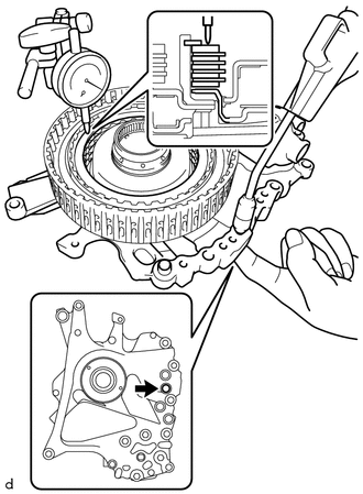
| | Cover Oil Hole |
Pack Clearance (Reference):
0.27 to 0.73 mm (0.0106 to 0.0287 in.)
HINT:
- Cover the location shown in the illustration with your finger when applying compressed air.
- To find the clearance, measure in at least 3 locations and average the results.
If the clearance is not as specified, replace the C-3 and C-4 clutch assembly.
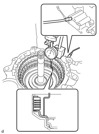
15. INSPECT CLEARANCE OF C-1 CLUTCH
HINT:
-
TMC (TOYOTA) Made, AW (AISIN AW) Made and TMMWV (TOYOTA) Made components can be identified by the differing locations where the serial number is stamped.
*a
TMC Made
*b
AW, TMMWV Made
-
for AW, TMMWV Made:
-
Refer to introduction and check the serial number. Confirm the factory at which the automatic transaxle assembly was manufactured according to the following table.
Serial Number
Factory
##6########
for AW (AISIN AW) Made
##A########
for TMMWV Made
-
Refer to introduction and check the serial number. Confirm the factory at which the automatic transaxle assembly was manufactured according to the following table.
| (a) Using a dial indicator, measure the clearance of the C-1 clutch while applying compressed air (approximately 200 kPa (2.0 kgf/cm2, 29 psi)). Pack Clearance (Reference): 1.0 to 1.2 mm (0.0394 to 0.0472 in.) HINT:
If the clearance is not as specified, select an appropriate forward clutch flange so that the clearance will be within the specified range. Forward Clutch Flange Thickness: for TMC, AISIN AW Made:
|
|
16. INSPECT CLEARANCE OF B-1 BRAKE
HINT:
-
TMC (TOYOTA) Made, AW (AISIN AW) Made and TMMWV (TOYOTA) Made components can be identified by the differing locations where the serial number is stamped.
*a
TMC Made
*b
AW, TMMWV Made
-
for AW, TMMWV Made:
-
Refer to introduction and check the serial number. Confirm the factory at which the automatic transaxle assembly was manufactured according to the following table.
Serial Number
Factory
##6########
for AW (AISIN AW) Made
##A########
for TMMWV Made
-
Refer to introduction and check the serial number. Confirm the factory at which the automatic transaxle assembly was manufactured according to the following table.
| (a) Using a dial indicator, measure the clearance of the B-1 brake while applying compressed air (approximately 200 kPa (2.0 kgf/cm2, 29 psi)). Pack Clearance: 0.8 to 1.0 mm (0.0315 to 0.0394 in.) HINT: To find the clearance, measure in at least 3 locations and average the results. If the clearance is not as specified, select an appropriate No. 1 brake flange so that the clearance will be within the specified range. No. 1 Brake Flange Thickness: for TMC Made:
|
|
17. INSPECT CLEARANCE OF C-2 CLUTCH
HINT:
-
TMC (TOYOTA) Made, AW (AISIN AW) Made and TMMWV (TOYOTA) Made components can be identified by the differing locations where the serial number is stamped.
*a
TMC Made
*b
AW, TMMWV Made
-
for AW, TMMWV Made:
-
Refer to introduction and check the serial number. Confirm the factory at which the automatic transaxle assembly was manufactured according to the following table.
Serial Number
Factory
##6########
for AW (AISIN AW) Made
##A########
for TMMWV Made
-
Refer to introduction and check the serial number. Confirm the factory at which the automatic transaxle assembly was manufactured according to the following table.
| (a) Using a dial indicator, measure the clearance of the C-2 clutch while applying compressed air (approximately 400 kPa (4.1 kgf/cm2, 58 psi)). Piston Stroke: 0.8 to 1.0 mm (0.0315 to 0.0394 in.) HINT: To find the clearance, measure in at least 3 locations and average the results. If the clearance is not as specified, select an appropriate direct clutch flange so that the clearance will be within the specified range. Direct Clutch Flange Thickness: for TMC Made:
|
|
18. INSPECT CLEARANCE OF B-2 BRAKE
HINT:
-
TMC (TOYOTA) Made, AW (AISIN AW) Made and TMMWV (TOYOTA) Made components can be identified by the differing locations where the serial number is stamped.
*a
TMC Made
*b
AW, TMMWV Made
-
for AW, TMMWV Made:
-
Refer to introduction and check the serial number. Confirm the factory at which the automatic transaxle assembly was manufactured according to the following table.
Serial Number
Factory
##6########
for AW (AISIN AW) Made
##A########
for TMMWV Made
-
Refer to introduction and check the serial number. Confirm the factory at which the automatic transaxle assembly was manufactured according to the following table.
| (a) Using a dial indicator, measure the clearance of the B-2 brake while applying compressed air (approximately 200 kPa (2.0 kgf/cm2, 29 psi)). Piston Stroke: 1.0 to 1.2 mm (0.0394 to 0.0472 in.) HINT: To find the clearance, measure in at least 3 locations and average the results. If the clearance is not as specified, select an appropriate 2nd brake brake flange so that the clearance will be within the specified range. HINT: There are 7 2nd brake brake flanges of different thicknesses available. 2nd Brake Brake Flange Thickness: for TMC Made:
|
|
READ NEXT:
 Reassembly
REASSEMBLY PROCEDURE 1. BEARING POSITION Check bearing position and installation direction. Thrust Needle Roller Bearing and Bearing Race Diameter: Mark Front Side Thrust Bearing Race Diameter
Components
COMPONENTS ILLUSTRATION *1 DRIVE MODE SELECT SWITCH (COMBINATION SWITCH ASSEMBLY) *2 INSTRUMENT CLUSTER FINISH PANEL ASSEMBLY
SEE MORE:
Inspection
INSPECTION PROCEDURE 1. INSPECT POWER WINDOW REGULATOR MOTOR ASSEMBLY (FOR DRIVER DOOR) (a) Connect a positive (+) lead from the auxiliary battery to connector terminal 2. NOTICE: Do not connect a positive (+) lead from the auxiliary battery to any terminal other than terminal 2 to avoid damaging
System Description
SYSTEM DESCRIPTION FUNCTION OF COMPONENTS (a) The parking support brake system consists of the following components: Component Function Clearance Warning ECU Assembly
Sends the drive force request signals and control status signals to the hybrid vehicle control ECU and skid control ECU
