Lexus ES: Installation
INSTALLATION
CAUTION / NOTICE / HINT
NOTICE:
-
Before replacing the main body ECU (multiplex network body ECU), refer to Registration.
SMART ACCESS SYSTEM WITH PUSH-BUTTON START(for Start Function, Gasoline Model):
Click here

SMART ACCESS SYSTEM WITH PUSH-BUTTON START(for Start Function, HV Model):
Click here
- After the main body ECU (multiplex network body ECU) has been replaced, the automatic light control system will not operate until the engine is started.
PROCEDURE
1. INSTALL MAIN BODY ECU (MULTIPLEX NETWORK BODY ECU)
NOTICE:
- Make sure that the connecting surfaces are free of foreign matter.
- Do not touch the main body ECU (multiplex network body ECU) connector.
(a) Set the main body ECU (multiplex network body ECU) to the position where the guide of the main body ECU (multiplex network body ECU) contacts the housing sidewall of the instrument panel junction block assembly as shown in the illustration.
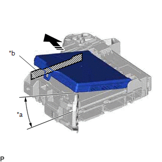
| *a | 20° or more |
| *b | Housing Sidewall |
 | Set in this Direction |
HINT:
Make sure to keep the angle at 20° or more as shown in the illustration.
(b) Slide the main body ECU (multiplex network body ECU) along the housing sidewall as shown in the illustration and engage the 2 guides.
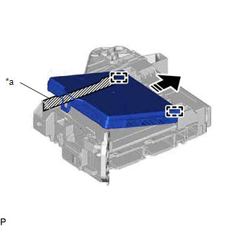
| *a | Housing Sidewall |
| | Slide in this Direction |
(c) While keeping the main body ECU (multiplex network body ECU) in contact with side A of the instrument panel junction block assembly (axis of rotation), lower it as shown in the illustration.
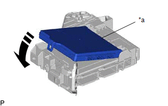
| *a | Side A |
| | Install in this Direction |
(d) Press the push area until the claw engages to install the main body ECU (multiplex network body ECU).
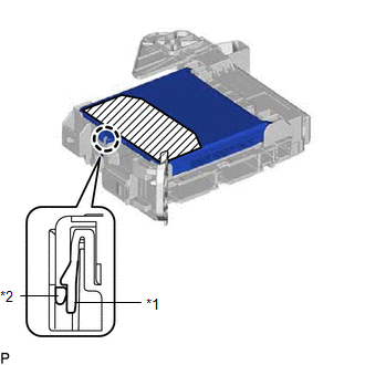
| *1 | Instrument Panel Junction Block Assembly |
| *2 | Main Body ECU (Multiplex Network Body ECU) |
 | Push Area |
NOTICE:
- Make sure to press only the push area.
- Confirm the engagement of the main body ECU (multiplex network body ECU) and instrument panel junction block assembly by listening for the click sound of the lock engaging.
HINT:
If a click sound cannot be heard, visually check the engagement of the lock. The engagement can also be confirmed if the main body ECU (multiplex network body ECU) and instrument panel junction block assembly are flush.
2. INSTALL WIRING HARNESS CLAMP BRACKET
(a) Engage the guide.
(b) Install the wiring harness clamp bracket with the nut.
Torque:
8.0 N·m {82 kgf·cm, 71 in·lbf}
3. INSTALL INSTRUMENT PANEL JUNCTION BLOCK ASSEMBLY WITH MAIN BODY ECU
(a) Connect the 2 connectors and pull down the 2 lock levers to engage the 2 claws and lock the connector as shown in the illustration.
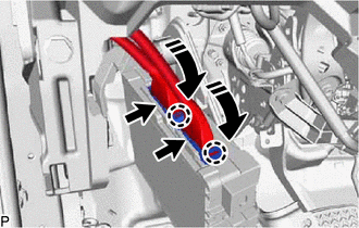
| | Install in this Direction |
NOTICE:
Be sure to connect the connector securely.
(b) Engage the clamp.
(c) Engage the clamp.
(d) Engage the claw and guide to install the instrument panel junction block assembly with main body ECU.
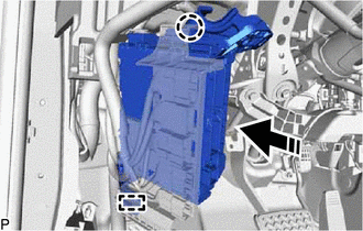
| | Install in this Direction |
(e) Install the 2 nuts.
Torque:
8.0 N·m {82 kgf·cm, 71 in·lbf}
(f) Connect each connector.
(g) Connect the 2 connectors and raise the 2 lock levers to engage the 2 claws and lock the connector as shown in the illustration.
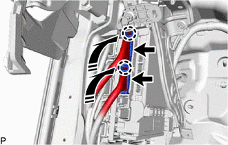
| | Install in this Direction |
NOTICE:
Be sure to connect the connector securely.
(h) Engage the clamp.
(i) Connect each connector.
4. INSTALL HYBRID VEHICLE CONTROL ECU (for HV Model)
Click here
5. INSTALL NO. 3 INSTRUMENT PANEL TO COWL BRACE SUB-ASSEMBLY
Click here
6. INSTALL LOWER NO. 1 INSTRUMENT PANEL AIRBAG ASSEMBLY
Click here
READ NEXT:
 Removal
REMOVAL CAUTION / NOTICE / HINT The necessary procedures (adjustment, calibration, initialization, or registration) that must be performed after parts are removed and installed, or replaced during mai
Components
COMPONENTS ILLUSTRATION *A for HV Model - - *1 HYBRID VEHICLE CONTROL ECU *2 INSTRUMENT PANEL JUNCTION BLOCK ASSEMBLY WITH MAIN BODY ECU *3 NO. 3 INSTRUMENT PANEL TO COWL BRA
SEE MORE:
Visual Mute Signal Circuit between Radio Receiver and Multi-display
DESCRIPTION The radio receiver assembly sends a visual mute signal to the multi-display assembly. As a result, a black screen is displayed when the screen changes so that noise and distorted images are not displayed. When an open exists in the circuit, noise and distorted images will be displayed in
Actuator Supply Voltage "A" Circuit Short to Ground or Open (P065714)
DESCRIPTION The electronic throttle control system has a dedicated power supply circuit. The voltage (+BM) is monitored and when it is low (less than 4 V), the ECM determines that there is a malfunction in the electronic throttle control system and cuts off the current to the throttle actuator. When
