Lexus ES: Installation
INSTALLATION
PROCEDURE
1. INSTALL BATTERY VOLTAGE SENSOR
CAUTION:
Be sure to wear insulated gloves and protective goggles.
| (a) Install the battery voltage sensor to the HV battery with the bolt. Torque: 7.5 N·m {76 kgf·cm, 66 in·lbf} NOTICE:
|
|
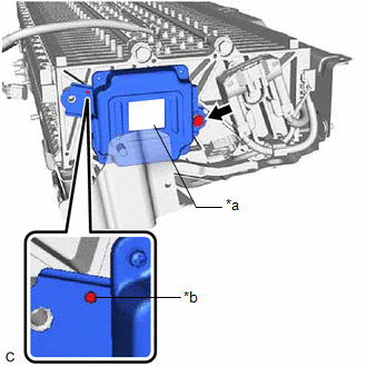
(b) Connect the battery voltage sensor connector.
NOTICE:
Make sure that the connector is connected securely.
2. INSTALL NO. 1 HV BATTERY SHIELD PANEL
CAUTION:
Be sure to wear insulated gloves and protective goggles.
(a) Pull back the rear No. 1 HV battery shield and install the No. 1 HV battery shield panel to the HV battery.
(b) Install the bolt and nut.
Torque:
7.5 N·m {76 kgf·cm, 66 in·lbf}
(c) Connect the battery voltage sensor connector.
(d) Engage the clamp.
3. INSTALL UPPER HV BATTERY COVER SUB-ASSEMBLY
CAUTION:
Be sure to wear insulated gloves and protective goggles.
(a) Install the upper HV battery cover sub-assembly to the HV battery with the 8 bolts and 4 nuts.
Torque:
7.5 N·m {76 kgf·cm, 66 in·lbf}
4. INSTALL HV BATTERY
Click here .gif)
READ NEXT:
 Combination Switch
ComponentsCOMPONENTS ILLUSTRATION *1 EV DRIVE MODE SWITCH (NO. 3 COMBINATION SWITCH ASSEMBLY) - - InspectionINSPECTION PROCEDURE 1. INSPECT EV DRIVE MODE SWITCH (NO. 3 COMBINATION SWITC
Components
COMPONENTS ILLUSTRATION *1 RESERVE TANK CAP *2 DRAIN COCK PLUG *3 NO. 1 ENGINE UNDER COVER - -
SEE MORE:
Light Sensor Circuit (B1244)
DESCRIPTION The automatic light control sensor detects ambient light. The sensor creates an electrical signal based on the amount of light detected, and sends the signal to the main body ECU (multiplex network body ECU). The main body ECU (multiplex network body ECU) turns on or off the headlights a
Removal
REMOVAL CAUTION / NOTICE / HINT The necessary procedures (adjustment, calibration, initialization or registration) that must be performed after parts are removed and installed, or replaced during fuel pump assembly removal/installation are shown below. Necessary Procedures After Parts Removed/Instal
