Lexus ES: Combination Switch
Components
COMPONENTS
ILLUSTRATION
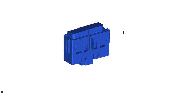
| *1 | EV DRIVE MODE SWITCH (NO. 3 COMBINATION SWITCH ASSEMBLY) | - | - |
Inspection
INSPECTION
PROCEDURE
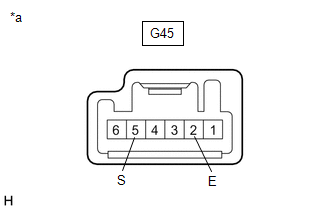
1. INSPECT EV DRIVE MODE SWITCH (NO. 3 COMBINATION SWITCH ASSEMBLY)
(a) Inspect EV mode switch (No. 2 combination switch assembly)
| (1) Measure the resistance according to the value(s) in the table below. Standard Resistance:
If the result is not as specified, replace the EV drive mode switch (No. 3 combination switch assembly). |
|
READ NEXT:
 Components
COMPONENTS ILLUSTRATION *1 RESERVE TANK CAP *2 DRAIN COCK PLUG *3 NO. 1 ENGINE UNDER COVER - -
On-vehicle Inspection
ON-VEHICLE INSPECTION CAUTION / NOTICE / HINT CAUTION: To avoid the danger of being burned, do not remove the reserve tank cap while the coolant (for inverter) is still hot. Pressurized, hot coolant (
SEE MORE:
System Description
SYSTEM DESCRIPTION POWER WINDOW CONTROL SYSTEM DESCRIPTION (a) The power window control system controls the power window operation using the power window regulator motor assemblies. The main controls of this system are the multiplex network master switch assembly (mounted on the driver door), power
Test Mode Procedure
TEST MODE PROCEDURE *1 Rear Disc Brake Piston *2 Nut *a The nut moves inward in pad replacement mode REAR BRAKE PAD REPLACEMENT MODE HINT: When replacing the rear disc brake pad and rear disc, since the nut inside the rear disc brake cylinder assembly is in an advanced position,
