
Lexus ES: Installation
INSTALLATION
PROCEDURE
1. INSTALL BATTERY COOLING BLOWER BRACKET
(a) Install the battery cooling blower bracket to the battery cooling blower assembly with the 3 bolts.
Torque:
7.5 N·m {76 kgf·cm, 66 in·lbf}
(b) Engage the clamp.
2. INSTALL BATTERY COOLING BLOWER ASSEMBLY
(a) Install the battery cooling blower assembly to the HV battery with the bolt and nut.
Torque:
7.5 N·m {76 kgf·cm, 66 in·lbf}
NOTICE:
- Be sure not to touch the fan part of the battery cooling blower assembly.
- Do not lift the battery cooling blower assembly using the wire harness.
(b) Connect the battery cooling blower assembly connector.
3. INSTALL NO. 1 HYBRID BATTERY INTAKE DUCT
(a) Install the No. 1 hybrid battery intake duct to the battery cooling blower assembly with the 2 clips.
(b) Engage the 2 clamps.
4. INSTALL REAR SEAT CUSHION LEG SUB-ASSEMBLY
| (a) Temporarily install the rear seat cushion leg sub-assembly with the 6 bolts. |
|
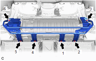
(b) Fully tighten the 6 bolts in the order shown in the illustration.
Torque:
16 N·m {163 kgf·cm, 12 ft·lbf}
5. INSTALL REAR UNDER COVER
(a) Engage the 2 guides.
(b) Engage the 2 clips to install the rear under cover to the rear seat cushion leg sub-assembly.
6. INSTALL REAR UNDER SIDE COVER LH
(a) Engage the claw, 5 clips and guide.
(b) Install the rear under side cover LH with the 2 clips.
7. INSTALL REAR DOOR SCUFF PLATE LH
Click here .gif)
8. INSTALL REAR UNDER SIDE COVER RH
(a) Engage the claw, 5 clips and guide.
(b) Install the rear under side cover RH with the 2 clips.
9. INSTALL REAR DOOR SCUFF PLATE RH
HINT:
Use the same procedure as for the LH side.
10. INSTALL REAR SEAT CUSHION LOCK HOOK
Click here
11. INSTALL REAR SEAT CUSHION ASSEMBLY
Click here
READ NEXT:
 Battery Cooling Filter
ComponentsCOMPONENTS ILLUSTRATION *1 NO. 1 HV BATTERY INTAKE FILTER *2 BATTERY SERVICE HOLE COVER
Components
COMPONENTS ILLUSTRATION *1 BATTERY SERVICE HOLE COVER *2 SERVICE PLUG GRIP ILLUSTRATION *1 CONNECTOR COVER ASSEMBLY *2 ENGINE ROOM MAIN WIRE Tightening torque for "Major
SEE MORE:
Rain Sensor Malfunction (B1400)
DESCRIPTION This DTC is stored when the rain sensor detects an internal malfunction. DTC No. Detection Item DTC Detection Condition Trouble Area Memory DTC Output from B1400 Rain Sensor Malfunction
IG power source voltage is 9.5 V or more
Either of the following is dete
Components
COMPONENTS ILLUSTRATION *1 COWL SIDE TRIM BOARD LH *2 FRONT DOOR OPENING TRIM COVER LH *3 FRONT DOOR SCUFF PLATE LH *4 INSTRUMENT SIDE PANEL LH *5 LOWER INSTRUMENT PANEL FINISH PANEL SUB-ASSEMBLY *6 NO. 1 INSTRUMENT PANEL UNDER COVER SUB-ASSEMBLY *7 PANORAMIC VIEW
