Lexus ES: System Diagram
Lexus ES (XZ10) Service Manual / Engine & Hybrid System / A25a-fxs (emission Control) / Emission Control System / System Diagram
SYSTEM DIAGRAM
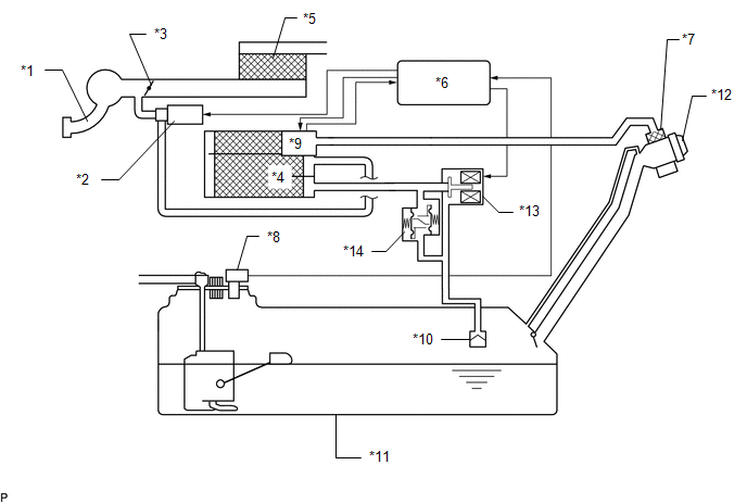
| *1 | Intake Manifold | *2 | Purge Valve (Purge VSV) |
| *3 | Throttle Valve | *4 | Canister (Charcoal Canister Assembly) |
| *5 | Air Cleaner | *6 | ECM |
| *7 | Canister Filter | *8 | Fuel Tank Pressure Sensor (Vapor Pressure Sensor Assembly) |
| *9 | Canister Pump Module (Leak Detection Pump Sub-assembly) - Canister Pressure Sensor - Pump Motor - Vent Valve | *10 | Cut-off Valve |
| *11 | Fuel Tank Assembly | *12 | Fuel Tank Cap Assembly |
| *13 | Fuel Vapor Containment Valve (Fuel Tank Solenoid Main Valve Assembly) | *14 | Fuel Outlet Valve (Relief Valve) |
READ NEXT:
 On-vehicle Inspection
ON-VEHICLE INSPECTION CAUTION / NOTICE / HINT CAUTION: To prevent injury due to contact with an operating cooling fan, keep your hands and clothing away from the cooling fans when working in the engin
Fuel Tank Cap
InspectionINSPECTION PROCEDURE 1. INSPECT FUEL TANK CAP ASSEMBLY (a) Visually check that the fuel tank cap assembly and gasket are not deformed or damaged. If the result is not as specified, repla
SEE MORE:
Outside Vehicle
OUTSIDE VEHICLE
These are maintenance and inspection items that are considered to be
the owner's responsibility.
The owner can do them or they can have them done at a service center.
These items include those that should be checked on a daily basis, those
that in most cases
Data List / Active Test
DATA LIST / ACTIVE TEST DATA LIST NOTICE: In the table below, the values listed under "Normal Condition" are reference values. Do not depend solely on these reference values when deciding whether a part is faulty or not. HINT: Using the Techstream to read the Data List allows the values or states of
© 2016-2026 Copyright www.lexguide.net
