Lexus ES: Installation
INSTALLATION
CAUTION / NOTICE / HINT
NOTICE:
This procedure includes the installation of small-head bolts. Refer to Small-Head Bolts of Basic Repair Hint to identify the small-head bolts.
Click here .gif)
PROCEDURE
1. INSTALL FUEL PRESSURE SENSOR
HINT:
Perform "Inspection After Repair" after replacing the fuel pressure sensor.
Click here
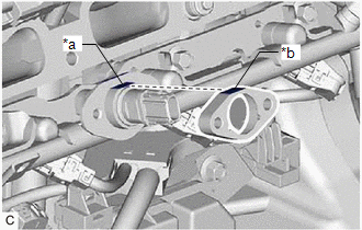
| (a) Temporarily install a new fuel pressure sensor to the fuel delivery pipe as shown in the illustration. NOTICE: Make sure that the cutout of the fuel delivery pipe is aligned with the cutout of the fuel pressure sensor. |
|
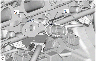
| (b) Temporarily install the No. 1 fuel pressure sensor holder to the fuel delivery pipe as shown in the illustration. NOTICE: Make sure that the cutout of the fuel pressure sensor is aligned with the cutout of the No. 1 fuel pressure sensor holder. |
|
(c) Using an 8 mm socket wrench, install the 2 bolts.
Torque:
10 N·m {102 kgf·cm, 7 ft·lbf}
(d) Connect the fuel pressure sensor connector.
2. INSTALL INTAKE MANIFOLD
Click here
3. CONNECT CABLE TO NEGATIVE BATTERY TERMINAL
Click here
4. INSPECT FOR FUEL LEAK
Click here
5. PERFORM INITIALIZATION
(a) Perform "Inspection After Repair" after replacing the fuel pressure sensor.
Click here
READ NEXT:
 Components
COMPONENTS ILLUSTRATION *1 REAR SEAT INNER BELT ASSEMBLY LH *2 REAR CENTER SEAT LAP TYPE BELT ASSEMBLY *3 WASHER *4 REAR SEAT CUSHION ASSEMBLY *5 REAR SEAT CUSHION LOCK HOOK
Disassembly
DISASSEMBLY CAUTION / NOTICE / HINT NOTICE: Do not disconnect the tube shown in the illustration when disassembling the fuel suction tube with pump and gauge assembly. Doing so will cause reassembly o
SEE MORE:
Inspection
INSPECTION PROCEDURE 1. INSPECT OUTER MIRROR RH (a) Check the outer mirror heater operation. (1) Measure the resistance according to the value(s) in the table below. Standard Resistance: Tester Connection Condition Specified Condition 1 - 2 25°C (77°F) 3.8 to 5.8 Ω If the re
Removal
REMOVAL CAUTION / NOTICE / HINT The necessary procedures (adjustment, calibration, initialization, or registration) that must be performed after parts are removed and installed, or replaced during outer rear view mirror assembly with cover removal/installation are shown below. Necessary Procedure Af
