Lexus ES: Installation
INSTALLATION
PROCEDURE
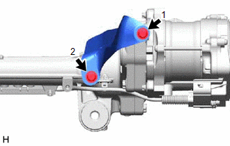
1. INSTALL STEERING GEAR HEAT INSULATOR (for 2GR-FKS)
| (a) Install the steering gear heat insulator to the rack and pinion power steering gear assembly with the 2 bolts in the order shown in the illustration. Torque: 8.0 N·m {82 kgf·cm, 71 in·lbf} |
|
2. INSTALL TIE ROD ASSEMBLY LH
| (a) Install the lock nut and tie rod assembly LH to the rack and pinion power steering gear assembly until the matchmarks are aligned. HINT: After adjusting the toe-in, tighten the lock nut. |
|
.png)
3. INSTALL TIE ROD ASSEMBLY RH
HINT:
Perform the same procedure as for the LH side.
4. INSTALL RACK AND PINION POWER STEERING GEAR ASSEMBLY
(a) Install the rack and pinion power steering gear assembly to the front frame assembly with the 4 bolts and 4 new nuts.
Torque:
88 N·m {897 kgf·cm, 65 ft·lbf}
NOTICE:
Because the nut has its own stopper, do not turn the nut. Tighten the bolt with the nut secured.
5. INSTALL FRONT STABILIZER BAR WITH BRACKET
(a) Install the front stabilizer bar with the 2 front stabilizer links, front No. 1 stabilizer bracket LH, front No. 1 stabilizer bracket RH and 2 front No. 1 stabilizer bar bushings to the front frame assembly.
(b) Install the front No. 1 stabilizer bracket LH to the front frame assembly with the 2 bolts.
Torque:
44 N·m {449 kgf·cm, 32 ft·lbf}
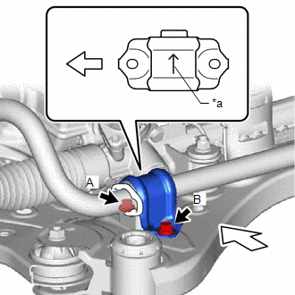
| *a | Arrow |
.png) | Front of the Vehicle |
NOTICE:
- Make sure to install the front No. 1 stabilizer bracket LH with its arrow facing the inside of the vehicle.
- Temporarily tighten the bolt (A) and (B), and then fully tighten the 2 bolts in the order of (A) and (B).
(c) Install the front No. 1 stabilizer bracket RH to the front frame assembly with the 2 bolts.
HINT:
Perform the same procedure as for the LH side.
6. INSTALL FRONT FRAME ASSEMBLY
Click here .gif)
7. REMOVE ENGINE HANGER (for 2GR-FKS)
Click here
8. CONNECT WIRE HARNESS
(a) Install the wire harness to the rack and pinion power steering gear assembly with the 2 bolts.
Torque:
10 N·m {102 kgf·cm, 7 ft·lbf}
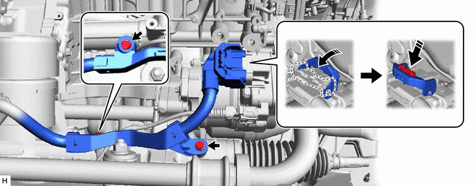
(b) Connect the wire harness connector to the rack and pinion power steering gear assembly.
HINT:
Make sure that the connector is fully inserted before rotating the lock lever to engage the lock.
9. INSTALL STEERING GEAR HEAT INSULATOR (for A25A-FXS)
| (a) Install the steering gear heat insulator to the rack and pinion power steering gear assembly with the 2 bolts in the order shown in the illustration. Torque: 8.0 N·m {82 kgf·cm, 71 in·lbf} |
|
10. INSTALL ENGINE ASSEMBLY WITH TRANSAXLE
for A25A-FXS: Click here
for 2GR-FKS: Click here
11. CONNECT TIE ROD ASSEMBLY LH
| (a) Connect the tie rod assembly LH to the steering knuckle LH with the nut. Torque: 49 N·m {500 kgf·cm, 36 ft·lbf} NOTICE:
|
|
.png)
(b) Install a new cotter pin.
12. CONNECT TIE ROD ASSEMBLY RH
HINT:
Perform the same procedure as for the LH side.
13. CONNECT STEERING INTERMEDIATE SHAFT ASSEMBLY
| (a) Align the matchmarks on the steering intermediate shaft assembly and rack and pinion power steering gear assembly. |
|
.png)
(b) Connect the steering intermediate shaft assembly to the rack and pinion power steering gear assembly.
(c) Install a bolt.
Torque:
35 N·m {357 kgf·cm, 26 ft·lbf}
14. INSTALL NO. 2 ENGINE UNDER COVER ASSEMBLY (for A25A-FXS)
Click here
15. INSTALL NO. 2 ENGINE UNDER COVER (for 2GR-FKS)
Click here
16. INSTALL NO. 3 ENGINE UNDER COVER (for 2GR-FKS)
Click here
17. INSTALL NO. 1 ENGINE UNDER COVER
for A25A-FXS: Click here
for 2GR-FKS: Click here
18. INSTALL FRONT WHEEL OPENING EXTENSION PAD LH
for A25A-FXS: Click here
for 2GR-FKS: Click here
19. INSTALL FRONT WHEEL OPENING EXTENSION PAD RH
for A25A-FXS: Click here
for 2GR-FKS: Click here
20. INSTALL FRONT WHEELS
Click here
21. TORQUE SENSOR ZERO POINT CALIBRATION
for HV Model: Click here
for Gasoline Model: Click here
READ NEXT:
 Installation
INSTALLATION PROCEDURE 1. INSTALL STEERING GEAR HEAT INSULATOR (for 2GR-FKS) (a) Install the steering gear heat insulator to the rack and pinion power steering gear assembly with the 2 bolts in the
Suspension
h1 {color:red;} h2 {color:blue;} h3 {color:green;}
SEE MORE:
Removal
REMOVAL CAUTION / NOTICE / HINT The necessary procedures (adjustment, calibration, initialization or registration) that must be performed after parts are removed and installed, or replaced during headlight assembly removal/installation are shown below. Necessary Procedure After Parts Removed/Install
Auto Down Operation does not Fully Open Power Window (Catch Protection Function is Activated)
DESCRIPTION If a door glass does not slide smoothly or a power window regulator motor assembly or door window regulator sub-assembly does not operate smoothly, the catch protection function may be triggered automatically, resulting in the auto down operation being unable to fully open the power wind
