Lexus ES: Crankshaft Position Sensor
Components
COMPONENTS
ILLUSTRATION
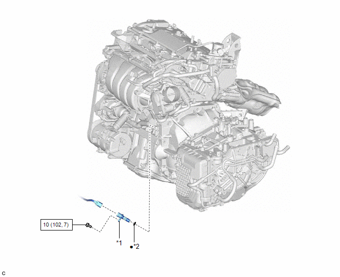
| *1 | CRANKSHAFT POSITION SENSOR | *2 | O-RING |
.png) | N*m (kgf*cm, ft.*lbf): Specified torque | ● | Non-reusable part |
Installation
INSTALLATION
CAUTION / NOTICE / HINT
NOTICE:
This procedure includes the installation of small-head bolts. Refer to Small-Head Bolts of Basic Repair Hint to identify the small-head bolts.
Click here .gif)
PROCEDURE
1. INSTALL CRANKSHAFT POSITION SENSOR
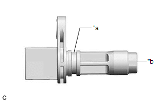
| *a | O-ring Groove |
| *b | Crankshaft Position Sensor Tip |
(a) Perform this procedure only when reusing the crankshaft position sensor.
(1) Clean the O-ring groove of the crankshaft position sensor.
NOTICE:
Make sure the O-ring groove is free of foreign matter.
(2) Install a new O-ring to the crankshaft position sensor.
NOTICE:
Set the O-ring on the tip of the crankshaft position sensor and roll it into the O-ring groove with bare hands to install it.
| (3) Check if the O-ring is twisted. HINT: Check the entire circumference of the seam of the O-ring for twisting. |
|
.png)
(b) Apply a light coat of engine oil to the O-ring of the crankshaft position sensor.
(c) Using an 8 mm socket wrench, install the crankshaft position sensor to the cylinder block sub-assembly with the bolt.
Torque:
10 N·m {102 kgf·cm, 7 ft·lbf}
NOTICE:
- If the crankshaft position sensor has been struck or dropped, replace it.
- Make sure that the O-ring is not cracked or moved out of place when installing the crankshaft position sensor.
(d) Connect the crankshaft position sensor connector.
2. INSTALL STARTER ASSEMBLY
Click here
READ NEXT:
 Ecm
Ecm
InstallationINSTALLATION PROCEDURE 1. INSTALL NO. 2 ECM BRACKET (a) Install the No. 2 ECM bracket to the ECM with the 2 screws. Torque: 4.5 N·m {46 kgf·cm, 40 in·lbf} 2. INSTALL NO. 1 ECM BRACKET
Engine Coolant Temperature Sensor
ComponentsCOMPONENTS ILLUSTRATION *1 ENGINE COOLANT TEMPERATURE SENSOR - - ● Non-reusable part - - RemovalREMOVAL CAUTION / NOTICE / HINT The necessary procedures (adjustmen
Ignition Coil And Spark Plug
RemovalREMOVAL CAUTION / NOTICE / HINT The necessary procedures (adjustment, calibration, initialization or registration) that must be performed after parts are removed and installed, or replaced dur
SEE MORE:
System Diagram
SYSTEM DIAGRAM Communication Table Sender Receiver Signal Line Main Body ECU (Multiplex Network Body ECU) Sliding Roof ECU (Sliding Roof Drive Gear Sub-assembly)
Sliding roof operation permission signal
IG signal
Front door courtesy light switch assembly signal
Key-linked
Terminals Of Ecu
TERMINALS OF ECU CLEARANCE WARNING ECU ASSEMBLY (a) Disconnect the N41 clearance warning ECU assembly connector. (b) Measure the voltage and resistance on the wire harness side connector according to the value(s) in the table below. Terminal No. (Symbol) Wiring Color Terminal Description C
