
Lexus ES: Installation
INSTALLATION
PROCEDURE
1. INSTALL CHECK VALVE GROMMET
(a) Install a new check valve grommet to the brake booster assembly.
2. INSTALL VACUUM WARNING SWITCH ASSEMBLY
(a) Install the vacuum warning switch assembly to the brake booster assembly as shown in the illustration.
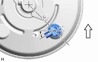
| *a | 30° +/- 20° |
.png) | Up |
(b) Connect the connector to the vacuum warning switch assembly.
3. INSTALL BATTERY
Click here .gif)
READ NEXT:
 Installation
INSTALLATION PROCEDURE 1. INSTALL CHECK VALVE GROMMET (a) Install a new check valve grommet to the brake booster assembly. 2. INSTALL VACUUM WARNING SWITCH ASSEMBLY (a) Install the vacuum warning swit
On-vehicle Inspection
ON-VEHICLE INSPECTION PROCEDURE 1. INSPECT BRAKE FLUID LEVEL IN RESERVOIR Click here 2. INSPECT BRAKE BOOSTER ASSEMBLY Click here 3. INSPECT VACUUM WARNING SWITCH ASSEMBLY (a) Start the engine and
On-vehicle Inspection
ON-VEHICLE INSPECTION PROCEDURE 1. INSPECT BRAKE FLUID LEVEL IN RESERVOIR Click here 2. INSPECT BRAKE BOOSTER ASSEMBLY Click here 3. INSPECT VACUUM WARNING SWITCH ASSEMBLY (a) Start the engine an
SEE MORE:
Reverse Signal Circuit between Radio Receiver Assembly and Navigation ECU
DESCRIPTION This circuit includes the navigation ECU and radio receiver assembly. WIRING DIAGRAM PROCEDURE 1. CHECK HARNESS AND CONNECTOR (RADIO RECEIVER ASSEMBLY - NAVIGATION ECU) (a) Disconnect the G1 radio receiver assembly connector. (b) Disconnect the G14 navigation ECU connector. (c)
Data List / Active Test
DATA LIST / ACTIVE TEST DATA LIST NOTICE: In the table below, the values listed under "Normal Condition" are reference values. Do not depend solely on these reference values when deciding whether a part is faulty or not. HINT: Using the Techstream to read the Data List allows the values or states of
© 2016-2026 Copyright www.lexguide.net
