Lexus ES: Installation
INSTALLATION
PROCEDURE
1. INSTALL AIR FUEL RATIO SENSOR
HINT:
Perform "Inspection After Repair" after replacing the air fuel ratio sensor.
Click here .gif)
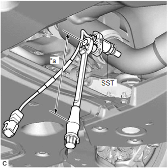
| (a) Using SST, install the air fuel ratio sensor to the front exhaust pipe assembly (TWC: Rear Catalyst). SST: 09224-00012 Torque: Specified tightening torque : 44 N·m {449 kgf·cm, 32 ft·lbf} NOTICE: If the air fuel ratio sensor has been struck or dropped, replace it. HINT:
|
|
| (b) Connect the air fuel ratio sensor connector. |
|
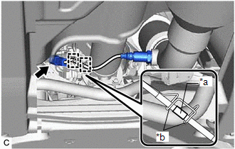
(c) Engage the 2 wire harness clamps so that the tube is positioned as shown in the illustration.
2. INSPECT FOR EXHAUST GAS LEAK
Click here
3. PERFORM INITIALIZATION
(a) Perform "Inspection After Repair" after replacing the air fuel ratio sensor.
Click here
READ NEXT:
 On-vehicle Inspection
ON-VEHICLE INSPECTION PROCEDURE 1. INSPECT CAM TIMING OIL CONTROL SOLENOID ASSEMBLY (a) Connect the Techstream to the DLC3. (b) Start the engine. (c) Turn the Techstream on. (d) Enter the following me
Removal
REMOVAL CAUTION / NOTICE / HINT NOTICE: This procedure includes the removal of small-head bolts. Refer to Small-Head Bolts of Basic Repair Hint to identify the small-head bolts. Click here PROCEDURE
SEE MORE:
Freeze Frame Data
FREEZE FRAME DATA FREEZE FRAME DATA HINT: The hybrid vehicle control ECU records vehicle and driving condition information as freeze frame data the moment a DTC is stored. It can be used for estimating or duplicating the vehicle conditions that were present when the malfunction occurred. (a) Connect
Installation
INSTALLATION PROCEDURE 1. INSTALL FUEL SENDER GAUGE ASSEMBLY (a) for Type A: (1) Engage the claw to install the fuel sender gauge assembly to the fuel suction tube with pump and gauge assembly. NOTICE: Be careful not to bend the arm of the fuel sender gauge assembly. (2) Engage the 2 clamps to conne
