Lexus ES: Removal
REMOVAL
CAUTION / NOTICE / HINT
NOTICE:
This procedure includes the removal of small-head bolts. Refer to Small-Head Bolts of Basic Repair Hint to identify the small-head bolts.
Click here .gif)
PROCEDURE
1. REMOVE NO. 1 ENGINE COVER SUB-ASSEMBLY
Click here
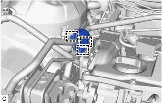
2. REMOVE NO. 3 BRAKE TUBE CLAMP
| (a) Disengage the 3 clamps and remove the piping clamp. NOTICE: When removing and installing the piping clamp, be careful not to deform the suction pipe sub-assembly or air conditioning tube and accessory assembly. |
|
| (b) Remove the bolt to separate the No. 3 brake tube clamp from the vehicle body. |
|
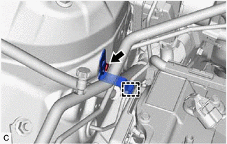
(c) Disengage the clamp and remove the No. 3 brake tube clamp.
3. REMOVE NO. 2 ENGINE COVER
Click here
4. REMOVE CAM TIMING OIL CONTROL SOLENOID ASSEMBLY
| (a) Disconnect the cam timing oil control solenoid assembly connector. |
|
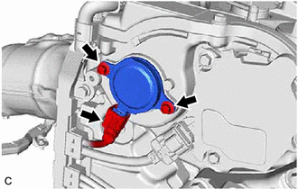
(b) Using an 8 mm socket wrench, remove the 2 bolts and cam timing oil control solenoid assembly from the No. 2 timing gear cover assembly.
NOTICE:
If the cam timing oil control solenoid assembly has been struck or dropped, replace it.
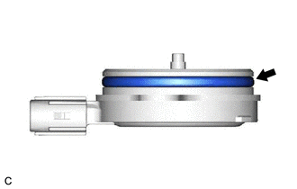
5. REMOVE O-RING
HINT:
Perform this procedure only when replacement of the O-ring is necessary.
| (a) Remove the O-ring from the cam timing oil control solenoid assembly. NOTICE:
|
|
READ NEXT:
 Inspection
INSPECTION PROCEDURE 1. INSPECT CAM TIMING OIL CONTROL SOLENOID ASSEMBLY (a) Check the resistance. (1) Measure the resistance according to the value(s) in the table below. Standard Resistance:
Installation
INSTALLATION CAUTION / NOTICE / HINT NOTICE: This procedure includes the installation of small-head bolts. Refer to Small-Head Bolts of Basic Repair Hint to identify the small-head bolts. Click here
Camshaft Oil Control Valve
ComponentsCOMPONENTS ILLUSTRATION *1 CAMSHAFT TIMING VALVE ASSEMBLY - - N*m (kgf*cm, ft.*lbf): Specified torque - - On-vehicle InspectionON-VEHICLE INSPECTION PROCEDURE 1. RE
SEE MORE:
Automatic High Beam System (B124B)
DESCRIPTION The main body ECU (multiplex network body ECU) determines the status of the automatic high beam system based on the automatic high beam system signal from the forward recognition camera. DTC No. Detection Item DTC Detection Condition Trouble Area DTC Output from B124B Au
Hybrid system precautions
Take care when handling the hybrid system, as it is a high voltage
system (about
650 V at maximum) as well as contains parts that become extremely hot when
the hybrid system is operating. Obey the warning labels attached to the vehicle.
System components
The illustration is an example for ex
