Lexus ES: Removal
REMOVAL
CAUTION / NOTICE / HINT
The necessary procedures (adjustment, calibration, initialization or registration) that must be performed after parts are removed and installed, or replaced during front exhaust pipe assembly (TWC: Rear Catalyst), center exhaust pipe assembly and tail exhaust pipe assembly removal/installation are shown below.
Necessary Procedures After Parts Removed/Installed/Replaced| Replaced Part or Performed Procedure | Necessary Procedure | Effect/Inoperative Function when Necessary Procedure not Performed | Link |
|---|---|---|---|
| Inspection After Repair |
| |
CAUTION:
To prevent burns, do not touch the engine, exhaust pipe or other high temperature components while the engine is hot.
.png)
PROCEDURE
1. REMOVE TAIL EXHAUST PIPE ASSEMBLY
CAUTION:
To prevent burns, do not touch the engine, exhaust pipe or other high temperature components while the engine is hot.
| (a) Remove the 2 bolts and disconnect the tail exhaust pipe assembly from the center exhaust pipe assembly. |
|
(b) Remove the tail exhaust pipe assembly from the 2 exhaust pipe supports.
(c) Remove the gasket from the center exhaust pipe assembly.
2. REMOVE TAIL EXHAUST PIPE ASSEMBLY LH
CAUTION:
To prevent burns, do not touch the engine, exhaust pipe or other high temperature components while the engine is hot.
| (a) Remove the 2 bolts and disconnect the tail exhaust pipe assembly LH from the center exhaust pipe assembly. |
|
(b) Remove the tail exhaust pipe assembly LH from the 2 exhaust pipe supports.
(c) Remove the gasket from the center exhaust pipe assembly.
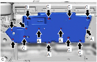
3. REMOVE FRONT FLOOR COVER LH
| (a) Type A: (1) Remove the 4 bolts and 4 clips (A). (2) Disengage the grommet (B) and 6 clips (C) to remove the front floor cover LH. |
|

| (b) Type B: (1) Remove the 3 bolts and 4 clips (A). (2) Disengage the grommet (B) and 6 clips (C) to remove the front floor cover LH. |
|
4. REMOVE FRONT FLOOR COVER RH
(a) Type A:
| (1) Remove the 3 bolts and 4 clips (A). |
|
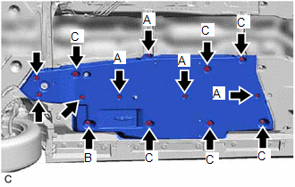
(2) Disengage the grommet (B) and 6 clips (C) to remove the front floor cover RH.
(b) Type B:
| (1) Remove the 4 bolts and 4 clips (A). |
|
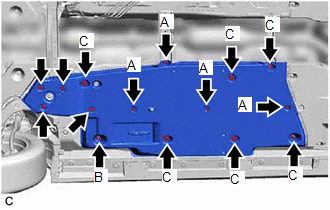
(2) Disengage the grommet (B) and 6 clips (C) to remove the front floor cover RH.
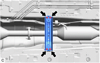
5. REMOVE FRONT CENTER FLOOR BRACE
| (a) Remove the 4 bolts and front center floor brace from the vehicle body. |
|
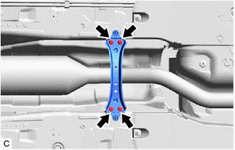
6. REMOVE CENTER FLOOR CROSSMEMBER BRACE
| (a) Remove the 4 bolts and center floor crossmember brace from the vehicle body. |
|
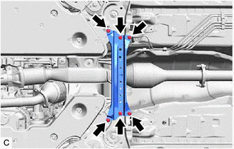
7. REMOVE CENTER EXHAUST PIPE ASSEMBLY
CAUTION:
To prevent burns, do not touch the engine, exhaust pipe or other high temperature components while the engine is hot.
| (a) Remove the 2 bolts, 2 nuts and disconnect the center exhaust pipe assembly from the front exhaust pipe assembly (TWC: Rear Catalyst). |
|
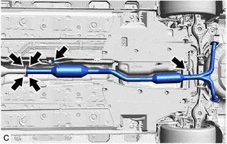
(b) Remove the center exhaust pipe assembly from the 2 exhaust pipe supports.
(c) Remove the gasket from the front exhaust pipe assembly (TWC: Rear Catalyst).
8. REMOVE BODY MOUNTING PLATE
| (a) Remove the 6 bolts and body mounting plate. |
|
9. REMOVE NO. 1 EXHAUST PIPE SUPPORT BRACKET (for Lower Side)
| (a) Remove the 2 nuts and No. 1 exhaust pipe support bracket (for Lower Side). |
|
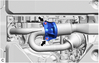
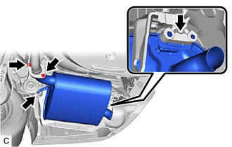
10. REMOVE FRONT EXHAUST PIPE ASSEMBLY (TWC: Rear Catalyst)
CAUTION:
To prevent burns, do not touch the engine, exhaust pipe or other high temperature components while the engine is hot.
| (a) Disconnect the 2 heated oxygen sensor connectors. |
|
.png)
(b) Disengage the 2 wire harness clamps.
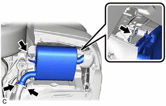
| (c) Remove the 2 bolts, 2 nuts and disconnect the front exhaust pipe assembly (TWC: Rear Catalyst) from the exhaust manifold (TWC: Front Catalyst). |
|
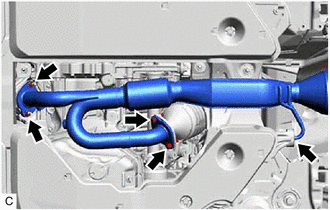
(d) Remove the front exhaust pipe assembly (TWC: Rear Catalyst) from the exhaust pipe support.
(e) Remove the 2 gaskets from the front exhaust pipe assembly (TWC: Rear Catalyst).
11. REMOVE HEATED OXYGEN SENSOR (for Bank 1)
Click here .gif)
12. REMOVE HEATED OXYGEN SENSOR (for Bank 2)
Click here
READ NEXT:
 Installation
INSTALLATION PROCEDURE 1. INSTALL HEATED OXYGEN SENSOR (for Bank 2) Click here 2. INSTALL HEATED OXYGEN SENSOR (for Bank 1) Click here 3. INSTALL FRONT EXHAUST PIPE ASSEMBLY (TWC: Rear Catalyst) (
Intake Air Control Valve(for Acis)
On-vehicle InspectionON-VEHICLE INSPECTION PROCEDURE 1. INSPECT INTAKE AIR CONTROL VALVE (for ACIS) (a) Disconnect the vacuum hose sub-assembly from the intake air control valve (for ACIS).
SEE MORE:
Brake Hold Switch
ComponentsCOMPONENTS ILLUSTRATION *1 BRAKE HOLD SWITCH (NO. 2 COMBINATION SWITCH ASSEMBLY) *2 REAR UPPER CONSOLE PANEL SUB-ASSEMBLY InspectionINSPECTION PROCEDURE 1. INSPECT BRAKE HOLD SWITCH (NO. 2 COMBINATION SWITCH ASSEMBLY) (a) Make sure that there is no looseness in the lockin
Check Bus 2 Lines for Short Circuit
DESCRIPTION There may be a short circuit between the CAN main bus lines and/or CAN branch lines when the resistance between terminals 18 (CA4H) and 17 (CA4L) of the central gateway ECU (network gateway ECU) is below 54 Ω. Symptom Trouble Area Resistance between terminals 18 (CA4H) and 17 (
