Lexus ES: Components
COMPONENTS
ILLUSTRATION
.png)
| *A | Type A | *B | Type B |
| *1 | FRONT FLOOR COVER RH | - | - |
.png) | N*m (kgf*cm, ft.*lbf): Specified torque | - | - |
ILLUSTRATION
.png)
| *A | Type A | *B | Type B |
| *1 | FRONT FLOOR COVER LH | - | - |
| | N*m (kgf*cm, ft.*lbf): Specified torque | - | - |
ILLUSTRATION
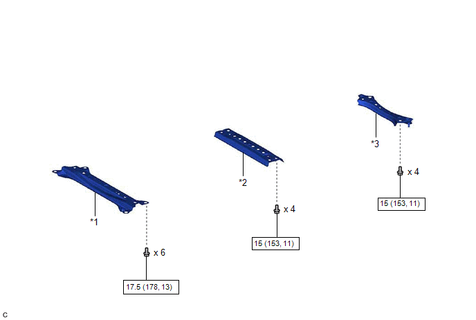
| *1 | BODY MOUNTING PLATE | *2 | CENTER FLOOR CROSSMEMBER BRACE |
| *3 | FRONT CENTER FLOOR BRACE | - | - |
| | N*m (kgf*cm, ft.*lbf): Specified torque | - | - |
ILLUSTRATION
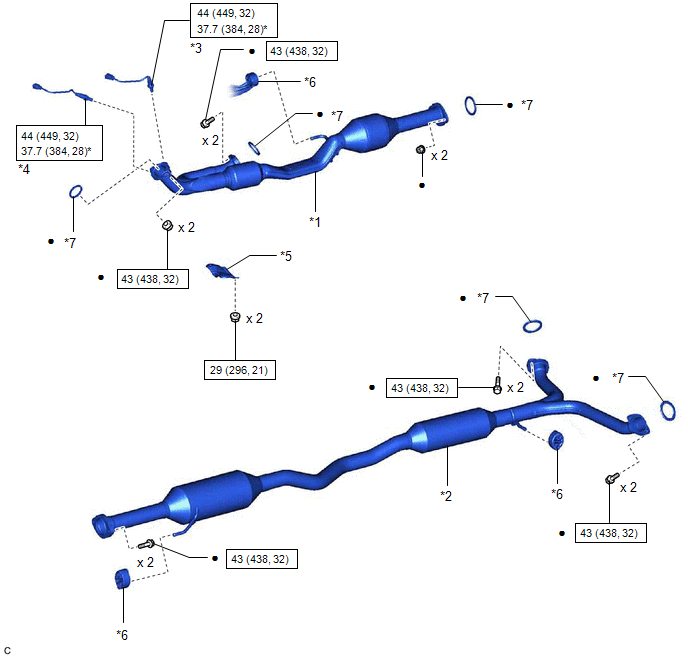
| *1 | FRONT EXHAUST PIPE ASSEMBLY (TWC: Rear Catalyst) | *2 | CENTER EXHAUST PIPE ASSEMBLY |
| *3 | HEATED OXYGEN SENSOR (for Bank 2) | *4 | HEATED OXYGEN SENSOR (for Bank 1) |
| *5 | NO. 1 EXHAUST PIPE SUPPORT BRACKET (for Lower Side) | *6 | EXHAUST PIPE SUPPORT |
| *7 | GASKET | - | - |
| | N*m (kgf*cm, ft.*lbf): Specified torque | * | For use with SST |
| ● | Non-reusable part | - | - |
ILLUSTRATION
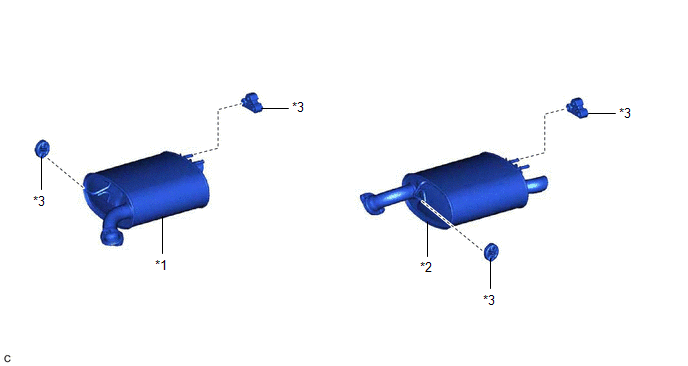
| *1 | TAIL EXHAUST PIPE ASSEMBLY | *2 | TAIL EXHAUST PIPE ASSEMBLY LH |
| *3 | EXHAUST PIPE SUPPORT | - | - |
READ NEXT:
 Removal
REMOVAL CAUTION / NOTICE / HINT The necessary procedures (adjustment, calibration, initialization or registration) that must be performed after parts are removed and installed, or replaced during fron
Installation
INSTALLATION PROCEDURE 1. INSTALL HEATED OXYGEN SENSOR (for Bank 2) Click here 2. INSTALL HEATED OXYGEN SENSOR (for Bank 1) Click here 3. INSTALL FRONT EXHAUST PIPE ASSEMBLY (TWC: Rear Catalyst) (
Intake Air Control Valve(for Acis)
On-vehicle InspectionON-VEHICLE INSPECTION PROCEDURE 1. INSPECT INTAKE AIR CONTROL VALVE (for ACIS) (a) Disconnect the vacuum hose sub-assembly from the intake air control valve (for ACIS).
SEE MORE:
ECU Malfunction (C1611)
DESCRIPTION If the clearance warning ECU assembly detects an internal malfunction during self-diagnosis, DTC C1611 is stored. DTC No. Detection Item DTC Detection Condition Trouble Area C1611 ECU Malfunction When either of the following conditioon is met:
Sub-CPU abnormal signal
No Response from ID BOX (B2789)
DESCRIPTION This DTC is stored when LIN communication between the certification ECU (smart key ECU assembly) and ID code box (immobiliser code ECU) stops for 10 seconds or more. DTC No. Detection Item DTC Detection Condition Trouble Area B2789 No Response from ID BOX No communicatio
