
Lexus ES: Components
COMPONENTS
ILLUSTRATION
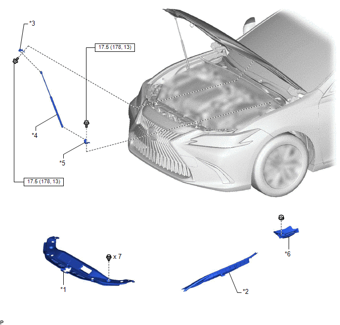
| *1 | COOL AIR INTAKE DUCT SEAL | *2 | FRONT FENDER SPLASH SHIELD SUB-ASSEMBLY |
| *3 | HOOD STAY BRACKET | *4 | HOOD SUPPORT ASSEMBLY |
| *5 | HOOD SUPPORT BRACKET | *6 | NO. 3 COWL TOP PANEL INSULATOR |
.png) | N*m (kgf*cm, ft.*lbf): Specified torque | - | - |
READ NEXT:
 Removal
REMOVAL CAUTION / NOTICE / HINT HINT:
Use the same procedure for the RH side and LH side.
The following procedure is for the LH side.
PROCEDURE 1. REMOVE HOOD SUPPORT ASSEMBLY NOTICE:
Avoid
Installation
INSTALLATION CAUTION / NOTICE / HINT HINT:
Use the same procedure for the RH side and LH side.
The following procedure is for the LH side.
PROCEDURE 1. INSTALL HOOD SUPPORT BRACKET (a) Engage
Disposal
DISPOSAL PROCEDURE 1. DISPOSE OF HOOD SUPPORT ASSEMBLY (a) Secure the hood support assembly horizontally in a vise with the piston rod pulled out. (b) Wearing safety glasses, gradually cut a part w
SEE MORE:
PBD/PTL Pulse Sensor (B2222,B2225)
DESCRIPTION DTC B2222 is output when there is a malfunction in the door pulse sensor system inside the luggage closer motor assembly and a normal waveform is not input to the door pulse sensor during a power trunk lid operation. Also, this DTC is output when there is a malfunction in the power trunk
Installation
INSTALLATION CAUTION / NOTICE / HINT NOTICE: This procedure includes the installation of small-head bolts. Refer to Small-Head Bolts of Basic Repair Hint to identify the small-head bolts. Click here PROCEDURE 1. INSTALL EGR VALVE ASSEMBLY HINT: Perform "Inspection After Repair" after replacing the
© 2016-2026 Copyright www.lexguide.net
