Lexus ES: Removal
REMOVAL
CAUTION / NOTICE / HINT
The necessary procedures (adjustment, calibration, initialization, or registration) that must be performed after parts are removed and installed, or replaced during ignition coil assembly or spark plug removal/installation are shown below.
Necessary Procedures After Parts Removed/Installed/Replaced| Replaced Part or Performed Procedure | Necessary Procedure | Effect/Inoperative Function when Necessary Procedure not Performed | Link |
|---|---|---|---|
| Inspection after repair |
| |
PROCEDURE
1. REMOVE V-BANK COVER SUB-ASSEMBLY
Click here .gif)
2. REMOVE IGNITION COIL ASSEMBLY
| (a) Disconnect the 3 ignition coil assembly connectors. |
|
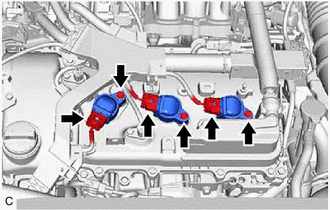
(b) Remove the 3 bolts and 3 ignition coil assemblies from the cylinder head cover sub-assembly LH.
NOTICE:
If an ignition coil assembly has been struck or dropped, replace it.
HINT:
Arrange the removed parts in the correct order.
| (c) Disengage the 4 clamps to separate the vacuum hose from the intake air surge tank assembly. |
|
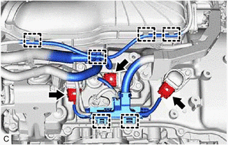
(d) Disengage the 2 wire harness clamps.
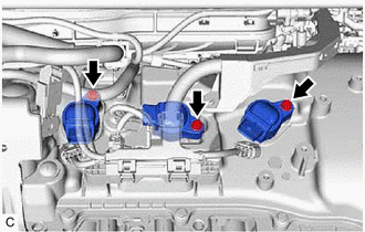
(e) Disconnect the 3 ignition coil assembly connectors.
| (f) Remove the 3 bolts and 3 ignition coil assemblies from the cylinder head cover sub-assembly. NOTICE: If an ignition coil assembly has been struck or dropped, replace it. HINT: Arrange the removed parts in the correct order. |
|
3. REMOVE SPARK PLUG
Click here
READ NEXT:
 Installation
INSTALLATION PROCEDURE 1. INSTALL SPARK PLUG Click here 2. INSTALL IGNITION COIL ASSEMBLY HINT: Perform "Inspection After Repair" after replacing an ignition coil assembly. Click here (a) Install
Parts Location
PARTS LOCATION ILLUSTRATION *1 ECM *2 NO. 1 ENGINE ROOM RELAY BLOCK AND NO. 1 JUNCTION BLOCK ASSEMBLY - INJ FUSE *3 IGNITION COIL ASSEMBLY *4 SPARK PLUG
SEE MORE:
Key-off Operation Function Operates even if Operating Conditions are not Satisfied
DESCRIPTION When the front doors are closed, each power window regulator motor assembly can be operated for approximately 45 seconds after the power switch is turned from on (IG) to off by receiving operation permission signals from the main body ECU (multiplex network body ECU). However, when appro
Power Window Motor Malfunction (B2311)
DESCRIPTION The power window regulator motor assemblies are operated by the multiplex network master switch assembly, power window regulator switch assembly or rear power window regulator switch assemblies. The power window regulator motor assemblies have motor, regulator and ECU functions. This DTC
