Lexus ES: Installation
INSTALLATION
CAUTION / NOTICE / HINT
NOTICE:
- Because the left and right front flexible hoses are not interchangeable, verify the part number when installing the front flexible hoses.
- When reusing the front flexible hoses, use the identification marks created during removal to install each front flexible hose to its original position.
HINT:
- Use the same procedure for the RH side and LH side.
- The following procedure is for the LH side.
PROCEDURE
1. INSTALL FRONT FLEXIBLE HOSE
NOTICE:
When installing the front flexible hose, minimize twisting of the hose.
|
(a) Install the front flexible hose with a new clip. NOTICE:
|
|
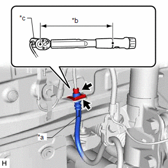
(b) Using a union nut wrench, connect the brake line to the front flexible hose while holding the front flexible hose with a wrench.
Torque:
Specified tightening torque :
15.2 N·m {155 kgf·cm, 11 ft·lbf}
NOTICE:
- Do not kink or damage the brake line.
- Do not allow any foreign matter such as dirt or dust to enter the brake line from the connecting parts.
HINT:
- Calculate the torque wrench reading when changing the fulcrum length
of the torque wrench.
Click here
.gif)
- When using a union nut wrench (fulcrum length of 22 mm (0.866 in.))
+ torque wrench (fulcrum length of 162 mm (6.38 in.)):
13.4 N*m (137 kgf*cm, 10 ft.*lbf)
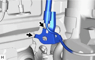
(c) Engage the 2 hooks to install the front speed sensor clamp bracket.
.png) |
Hook |
NOTICE:
Do not twist the front speed sensor wire harness when installing it.
|
(d) Install the front flexible hose and front speed sensor to the front shock absorber assembly with the bolt. Torque: 29 N·m {296 kgf·cm, 21 ft·lbf} NOTICE: Do not twist the front flexible hose when installing it. |
|
.png)
(e) Connect the front flexible hose to the front disc brake cylinder assembly with a new union bolt and a new gasket.
Torque:
29.4 N·m {300 kgf·cm, 22 ft·lbf}
NOTICE:
- Install the front flexible hose lock securely into the lock hole in the front disc brake cylinder assembly.
- Do not twist the front flexible hose when installing it.
2. CONNECT CABLE TO NEGATIVE AUXILIARY BATTERY TERMINAL (for HV Model)
(a) Connect the reservoir level switch connector.
(b) Connect the cable to the negative (-) auxiliary battery terminal.
Click here
3. BLEED BRAKE LINE
for HV Model: Click here
for Gasoline Model: Click here
4. INSTALL FRONT WHEEL
Click here
READ NEXT:
 Components
COMPONENTS
ILLUSTRATION
*1
FRONT DISC BRAKE ANTI-SQUEAL SHIM KIT
*2
FRONT DISC BRAKE PAD
*3
FRONT DISC BRAKE CYLINDER ASSEMB
Removal
REMOVAL
CAUTION / NOTICE / HINT
The necessary procedures (adjustment, calibration, initialization, or registration)
that must be performed after parts are removed and installed, or replaced during
SEE MORE:
Reassembly
REASSEMBLY CAUTION / NOTICE / HINT CAUTION: If the rear disc brake cylinder assembly has been disassembled, perform air bleeding for the rear disc brake cylinder assembly. for HV Model: Click here for Gasoline Model: Click here NOTICE:
Make sure not to scratch, damage or apply excessive force
Distance Control Switch Circuit
DESCRIPTION The vehicle-to-vehicle distance control switch is used to set the distance for vehicle-to-vehicle distance control mode. The vehicle-to-vehicle distance control switch is installed in the steering pad switch assembly. The vehicle-to-vehicle distance set value can be changed by operating
